So here comes the embarrasing question 🙂)
Pfarell, first off: thanks for all these great pix and for all the work you went through.
Since you did all this, for sure, copy-paste, "you've listened to them all, which one is BEST?" GLOL!
More seriously, would you mind sharing your experience with the various FEs and perhaps how you found they fare vs the original FE?
Many thanks if you find the time... if not, no issue at all and thanks anyway to have been part of this massive FE project.
Claude
Having written all that, despite having a (very personal wish) re alternative FEs, I realise that...
Whereas Pfarell did indeed a massive job, I take it someone else has done more builts than him on (all) these FEs and shouldn't been forgotten for his impressive work... Mark himself!
But then we already asked on his preferences... and he already answered that one.
At the time I wasn't having a deeper thought on this. Now, reading other's experience and based on my own experience with the original FE bypass, I came to the very personal conclusion - perhaps completely wrongly as I haven't tried the other FEs! - that one FE that may suit ME (and that's just ME) best is... either the original one... or (yes, I said I was done, but once you start tweaking, you never stop!) perhaps one that has very very few parts, includes a transformer, has trully excellent sounding parts (as the original has them) and very short signal paths, while "gain factor" is not that important in my very own case.
Bloody hell, I do now realise that the ones being very close friends to Mark might be the only ones to find out if my specs make sense.
Pfarell, should you be in that case, could you also for my very own curiosity share your POV on the - absolutely nonobtanium- Relentless? That's of course just to satisfy my curiosity... Looking at the pix, that one seems to correspond best to my very own specs... but again given what I am looking for, the original seems VERY hard to beat with its excellent parts and great sound match with the OS.
But then not building another of Mark's devices would be pity, argh!!
Big thanks to Mark and Pfarell: we are lucky to have been given these kinds of headache... and this wide choice of options to suit for sure anyone's preference, needs... and to cover future amps needs re FEs.
Claude
Last edited:
Wouldn't it be fun if there were a "VFET Front End Experimenter's Board" available both as Gerber files, and also sold to members through a Group Buy? It would have the same physical size and interface as all the existing Front End boards, including identical mounting holes. It would have PCB footprints for Euroblox wire-to-board connectors, and for the Edcor transformer. It might even have a Ground Plane on the bottom copper layer, for shielding purposes. And all the rest of it would be gloriously empty. Blank, naked, and desolate. Vast swaths of bare ground where builders could attach their own veroboard / stripboard / vectorboard circuitry with glue or silicone adhesive or Blue-Tac or stainless steel bolts. Presto, you can now roll your own VFET front end cards a lot more easily. Based on his early and enthusiastic campaigning for a vacuum tube Front End card, I imagine that member mbrennwa might be one candidate to head such an effort.
Mark Johnson—Throwing me under the bus!! 😀😀😀 And now a new project for Matthias (mbrennwa)! Wow! Bit cosmic there because when I do have my VFET amps up and running—they will be through the OSMC! (EPIC).
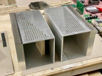
I love assisting in all efforts DIYaudio. And making the images is a special obsession on two fronts. So, thanks. Unfortunately—you can see the state of the VFET build on my end. It's up next! BUT—there's hope since our beloved 6L6 says the secret to completing any great DIY audio project is having a chassis (he says a lot of other smart things too 😀). I have a chassis(s). Pics reveal where I'm going with the project...
I will of course be sure to weigh in with my completely personal and perhaps meaningless observations with the FEs (as driven by a vinyl centric system). By comparison, certainly audio options is one of THE reasons to build M2X—the amps that just keep giving—having tried and retried all daughter boards therein, each with it's own character in my system—and with MJ making new stuff—M2X just keeps getting better. My favorite is stuff getting better. VFET offers the same possibilities for more insight and understanding, but with that VFET thing—I'm quite motivated to get them up and running—having the sample VFET amp here for pics and a test drive was super fun and it sounded fantastic.
Attachments
Last edited:
Yes, please!Wouldn't it be fun if there were a "VFET Front End Experimenter's Board" available both as Gerber files, and also sold to members through a Group Buy? It would have the same physical size and interface as all the existing Front End boards, including identical mounting holes. It would have PCB footprints for Euroblox wire-to-board connectors, and for the Edcor transformer. It might even have a Ground Plane on the bottom copper layer, for shielding purposes. And all the rest of it would be gloriously empty. Blank, naked, and desolate. ...
Presto, you can now roll your own VFET front end cards a lot more easily. Based on his early and enthusiastic campaigning for a vacuum tube Front End card, I imagine that member mbrennwa might be one candidate to head such an effort.

And might I suggest a dual footprint for Edcor PC series and Jensen JT-123-FLPCH?
All you have to do is find someone to do the work. I'm fully occupied myself, on other projects.
_
_
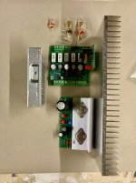
Well... attached is what I posted 4 months ago re FE installation, and of course what I did. I was worried about the negative sonic impact of connectors in the signal path, but that proved exagerated.
As one can see, I can easily install any FE board within a few minutes without having even to remove the VFET amp. I just need a small screw driver for this (and an allen key for the top plate screws). The very detailled process is:
1- Switch off the VFET amp (obviously!)
2- Unscrew the 4 screws holding the top plate to remove the latter
3- Unscrew at the 3 FE connectors the screws to release the signal and PS wires
4- Unscrew the 2 screws holding the FE board on its mounts to remove it
5- Reverse operation to install a FE board
6 - Do the same for the other channel
7- Switch on the VFET amp (obviously!)
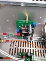
This is done in matter of minutes from the top of the amp and enables quick comparisons. To do it quickly and foolproof even in suboptimal evening form, I used blue connectors for the signal wires and big green ones for the PS wires. On top, I marked the "+" of each connector RED.
Now, all this was done for nearly nothing as I didn't play with FE boards rolling and only used this set up to compare VFET with vs VFET without FE stage. So far.
As Rega TT owner, I am part of another forum where some members came up with a perhaps interesting idea. The problem is for some to find the optimal (driving) belt or driving belt combinations. There is quite a variety of material available for the belt, each having a different sound impact. Now, no one with the right mind was ready to purchase all possible belts for 500$ to compare their sonic virtues. BUT someone came up with an idea: for each region (EU, US etc.), a single "test kit" was made available at the shop's level for members, comprising all belts for 500$. This kit could be sent to members for a nominal fee of less than 20$ including postage, to try the belts, so that each member could afterwards order and purchase his prefered belt.
So instead of spending 500$ to find out which belt is best (and not knowing what to do with the remaining ones), members did just spend 20$ to test by themselves... and say 50$ to later purchase their prefered belt. So spending 70$ instead of 50$ but having the fun of testing and the certainty to have what members felt is their prefered belt. But this relied on the shop running the risk and obviously is more work, whereas the shop here is far more busy already!
So no clue if that's wise or even applicable in a way or another, just thinking out loud... given trying all FE options amount to probably similar money if not more. On the other hand, all this might not really be necessary as we are lucky to have trustfull experienced members here who can report on their perceived sonic impact of each FE board and probably help each of us that way reducing our choice based on each one's needs and tastes (based on the said reports). So perhaps eachof us would only have a couple of options to try, still fun, still resonable money. If one tester would install his FEs the way I did it, it would be a child's play for him to compare the different FE options... provided of course they are all "at hand".
I hope this helps
Claude
As one can see, I can easily install any FE board within a few minutes without having even to remove the VFET amp. I just need a small screw driver for this (and an allen key for the top plate screws). The very detailled process is:
1- Switch off the VFET amp (obviously!)
2- Unscrew the 4 screws holding the top plate to remove the latter
3- Unscrew at the 3 FE connectors the screws to release the signal and PS wires
4- Unscrew the 2 screws holding the FE board on its mounts to remove it
5- Reverse operation to install a FE board
6 - Do the same for the other channel
7- Switch on the VFET amp (obviously!)
This is done in matter of minutes from the top of the amp and enables quick comparisons. To do it quickly and foolproof even in suboptimal evening form, I used blue connectors for the signal wires and big green ones for the PS wires. On top, I marked the "+" of each connector RED.
Now, all this was done for nearly nothing as I didn't play with FE boards rolling and only used this set up to compare VFET with vs VFET without FE stage. So far.
As Rega TT owner, I am part of another forum where some members came up with a perhaps interesting idea. The problem is for some to find the optimal (driving) belt or driving belt combinations. There is quite a variety of material available for the belt, each having a different sound impact. Now, no one with the right mind was ready to purchase all possible belts for 500$ to compare their sonic virtues. BUT someone came up with an idea: for each region (EU, US etc.), a single "test kit" was made available at the shop's level for members, comprising all belts for 500$. This kit could be sent to members for a nominal fee of less than 20$ including postage, to try the belts, so that each member could afterwards order and purchase his prefered belt.
So instead of spending 500$ to find out which belt is best (and not knowing what to do with the remaining ones), members did just spend 20$ to test by themselves... and say 50$ to later purchase their prefered belt. So spending 70$ instead of 50$ but having the fun of testing and the certainty to have what members felt is their prefered belt. But this relied on the shop running the risk and obviously is more work, whereas the shop here is far more busy already!
So no clue if that's wise or even applicable in a way or another, just thinking out loud... given trying all FE options amount to probably similar money if not more. On the other hand, all this might not really be necessary as we are lucky to have trustfull experienced members here who can report on their perceived sonic impact of each FE board and probably help each of us that way reducing our choice based on each one's needs and tastes (based on the said reports). So perhaps eachof us would only have a couple of options to try, still fun, still resonable money. If one tester would install his FEs the way I did it, it would be a child's play for him to compare the different FE options... provided of course they are all "at hand".
I hope this helps
Claude
Attachments

Last edited:
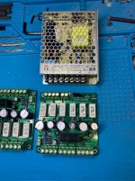
Your creations are professional and pieces of art too.Clearing off a lab bench this morning, I discovered this prototype from last year. I thought some readers might perhaps find it interesting.
It's a motherboard-daughterboard combination. The motherboard has a high gain, low noise amplifier (on the right) with several BNC output jacks, for good signal integrity into an oscilloscope. The daughterboards are early design studies / prototypes of a few different DC-to-DC voltage boosters, as used on the Marauder and Dreadnought front end cards. This fixture is intended to study the supply noise which the boosters do or don't inject onto the higher voltage supply output.
Those big black rectangles are Panasonic polypropylene capacitors, used for AC coupling between the cascaded stages of the amplifier. They create an LF corner frequency around 5 Hz if I recall correctly. Instead of having switchable gain, I simply plopped down separate, individual BNC jacks for +20dB, +40dB, and +60dB of gain. You might be able to see the labels on the silkscreen layer next to the jacks.
And that's how I decided which of the booster candidates, to put on Marauder & Dreadnought.
_
My box showed up last night. Very very well packaged thank you very much I do appreciate it. Hope to begin working on them before the end of the month.
I am declaring my Scourge builds a success. With some very modest tweaks to capacitors and sufficient run-in time over a few days, they are a pleasure to listen to. As I mention in my review over in the VFET builders thread, the cards have reached a state where I really don't want to tweak them any further. In some ways they sound similar to my Aleph J, another build which I love, and has remained untouched since it was completed.
This leaves me with a small quandary; I originally had plans to try a more extensive modification inspired by the Moffet Field version of the M2x FE cards. This needs to remain on hold, as I would rather not disturb the state of the Scourge boards as they are. Perhaps another intrepid amp builder might pick this up and run with it. The seeds for this idea may be found at The diyAudio First Watt M2x
This leaves me with a small quandary; I originally had plans to try a more extensive modification inspired by the Moffet Field version of the M2x FE cards. This needs to remain on hold, as I would rather not disturb the state of the Scourge boards as they are. Perhaps another intrepid amp builder might pick this up and run with it. The seeds for this idea may be found at The diyAudio First Watt M2x
Noob question about power supply for these boards
Can someone please ballpark for me the current draw of these boards?
I will be playing with all four boards in combo with yet-to-built Mofo monoblocks as my first foray into the world of SS amplification. (I've only previously built and tinkered with tube amps).
I gather that I need a 36V+/GND supply for these boards. I plan to feed each board via a linear psu and a Salas UltraBiB reg. But I'd like to know the current draw of the boards so I can get appropriately sized trafos and estimate the required size of the capacitor banks.
(p.s. I understand that I will need a separate psu's for the Mofos - I plan to build the 24V versions).
Also: if it's clear from the above that I'm clueless about something important, please clue me in!
cheers and many thanks in advance,
Derek
For members who might enjoy attempting to calculate / estimate the numbers requested in post #272, here are some reasonable assumptions you might make, that could help you calculate the currents.
Scourge: Assume all KSC3503 devices in this circuit, operate at Vbe=0.65 volts
Bulwark: Assume all 1N4448s operate at Vfwd=0.65 volts, all BJTs operate at |Vbe|=0.65
Marauder: Assume both opamp ICs draw their datasheet max current per amplifier {2134 is a dual}; assume JBOOST1's supply current drawn from POS_NORM, is less than or equal to (3.3x the current drawn from POS_BOOSTED). This is a conservative overestimate.
Dreadnought: Make all of the above Marauder assumptions, plus assume that all |Vbe| values equal 0.65 volts
Many thanks Mark -
I'll take a stab at estimating the current draw of the Scourge. The KSC3503 datasheet suggests that for Vbe of 0,65V we get just shy of 20 mA of current through the collector. There are 3 KSC3503, so that makes 60 mA in total. Is that right (or ballpark)?
If so, then even a 500 mA psu will be way more than enough for the Scourge. If the above is correct, I'll continue on and ballpark the other boards. I only want to build one pair of psu's that can be used to power all boards.
cheers and many thanks, Derek
Hi Derek,
You have a start at estimating the total current for the Scourge. However, you need to look at how two of the KSC3503 are used. You will find that two of these, Q3 and Q4, share the same single-ended class A current. There is also some small current consumed by the input resistors R6 and R7, and the LM285, though that is very small.
You have a start at estimating the total current for the Scourge. However, you need to look at how two of the KSC3503 are used. You will find that two of these, Q3 and Q4, share the same single-ended class A current. There is also some small current consumed by the input resistors R6 and R7, and the LM285, though that is very small.
To be safe just assume that every Front End card dissipates 4.5 watts or possibly less if you're extra lucky. Then Current = (Power / Voltage) = (4.5 / 36) = 125 milliamps or possibly less.
A 36V power supply rated for 500mA of output current (post 274), will thus be able to feed two Front End boards of any type, not just Scourge, AND that power supply will operate with a very comfortable margin of safety: a factor of two. Nice.
A 36V power supply rated for 500mA of output current (post 274), will thus be able to feed two Front End boards of any type, not just Scourge, AND that power supply will operate with a very comfortable margin of safety: a factor of two. Nice.
Many thanks TA.
Yes! Thanks! I suspected as much last night after noticing that the emitter of top NPN feeds current to the collector of the bottom NPN.
Given my present lack of understanding of SS amplifier circuits (which I plan/hope to remedy in the coming years), I think for my simple purpose of building a good-for-all-boards psu, my safest and easiest approach is to (1) assume (incorrectly) that all BJTs and opamps draw current directly from the psu; and (2) apply the assumptions provided by Mark. This will result in a potentially largish over estimation of total current draw. But I'm ok with that as I don't mind overbuilding the psu by a factor of x2 or x3 or even x5. I just want to avoid overbuilding by a factor of x20 or x30!
All that said, the lack of heatsinks should have clued me to the fact that these are low dissipation circuits and so must draw fairly modest current.
cheers, Derek
... You will find that two of these, Q3 and Q4, share the same single-ended class A current. ...
Yes! Thanks! I suspected as much last night after noticing that the emitter of top NPN feeds current to the collector of the bottom NPN.
Given my present lack of understanding of SS amplifier circuits (which I plan/hope to remedy in the coming years), I think for my simple purpose of building a good-for-all-boards psu, my safest and easiest approach is to (1) assume (incorrectly) that all BJTs and opamps draw current directly from the psu; and (2) apply the assumptions provided by Mark. This will result in a potentially largish over estimation of total current draw. But I'm ok with that as I don't mind overbuilding the psu by a factor of x2 or x3 or even x5. I just want to avoid overbuilding by a factor of x20 or x30!
All that said, the lack of heatsinks should have clued me to the fact that these are low dissipation circuits and so must draw fairly modest current.
cheers, Derek
Many thanks Mark. I didn't see your response before replying to TungstenAudio.
That makes thing even easier.
cheers, Derek
That makes thing even easier.
cheers, Derek
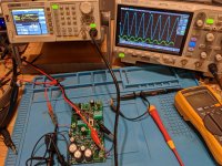
They're WORKING!
Finished stuffing all 4 pairs of boards this week and today mustered the bravery to fire them up. And all four pairs worked - Scourge, Bulwark, Marauder and Dreadnought.
Here's pic of a Dreadnought board under test. Green trace at bottom shows input of 1K sinewave at 2Vp-p. Top blue trace shows output of 13+ Vp-p into a 120K load resistor. And the phase inverter switches work too! Awesomeness.
Haven't listened to them yet. Still need to build the PSUs and figure out how I'll configure them as a preamp for use with yet to be built BIG MOFOs.
I have a suggestion for the diyAudio Store regarding the kits: the printing on some of the tiny ceramic caps is unreadable even with a magnifier. And some of them are in pF range, which isn't measurable by most DMMs (my Fluke can only go as low as 1nF and I'm not sure I'd trust it even for that). This wasn't a problem for me b/c I have a cheapish handheld LCR meter, but I don't imagine most people have an LCR meter. I think it would be helpful if those tiny caps were labelled in the kits. I don't know who at the Store to contact with the above suggestion, so I'm posting it here.
Can't wait to listen to these boards. Had a lot of fun building them. Many thanks Mark for sharing your designs!
cheers, Derek
Attachments
Wow!
I say again: wow!!
Fantastic job, Derek. You've accomplished great things -- some of those boards are reasonably complex, and you built every single one of them properly & correctly. Take a bow and treat yourself to a couple of delicious desserts or adult beverages, or maybe both.
Take your time and listen to your front end boards, according to whatever protocol YOU think is best -- don't be pressured or bullied into evaluating YOUR WORK on somebody else's schedule. Your hobby, your project(s), your agenda. They can perform their hobby projects, their way. And you can pursue your hobby projects your way. You have only one boss: you and no one else.
- Home
- Amplifiers
- Pass Labs
- Scourge, Bulwark, Marauder, Dreadnought "front end" cards for DIY VFET amp