I am currently getting ready to build an F4. Boards and most parts are in the house, but I would like to add/experiment with a little gain.
Is there a way to use one of these in an amp running on +-24V, or are there any future plans for front ends capable of this?
Ultimately I would like to try the original M2 as I already have the Edcors and matched Toshibas. 🙄
Is there a way to use one of these in an amp running on +-24V, or are there any future plans for front ends capable of this?
Ultimately I would like to try the original M2 as I already have the Edcors and matched Toshibas. 🙄
If you are feeling adventurous enough to convert one of these to +/– 24V, look at the Scourge. Compare this with the M2x Mountain View, which is designed to run on +/– 24V. I think you will find the conversion fairly straightforward.
These front end boards are designed for mechanical compatibility with the VFET chassis having UMS heatsinks, plus electrical compatibility with the VFET output follower cards and the VFET power supply.
Since the VFET amplifiers' power supply is a single ended configuration (+36V, GND), these front end boards are designed for a single ended supply. In their present form they won't work in a different, non-VFET, amplifier having a bipolar (+24V, -24V) power supply.
These front end boards certainly would work as a "line stage", mounted in their own small chassis with their own (+36V, GND) single ended power supply. Maximum available output signal from such a line stage would be about 14.5 volts RMS, which equals ±20.5 volts peak to peak. That fits quite nicely with the F4 specifications on FirstWatt's website which say that F4's maximum output before clipping is ±20 volts.
In fact, as long as you supply these front end cards with a clean (+36V, GND) single ended supply, it doesn't really matter which chassis you decide to mount them in. Put them inside another power amp? sure. Put them in their own chassis? certainly. Just provide a nice (+36V, GND) supply, avoid ground loops, route signal cables and power cables with care, and Bob's your uncle.
The final possibility is to redesign the circuits and relayout the PCBs, for use with a bipolar power supply. This may not be a simple monkey-see, monkey-do exercise in mindless copying: you'll also need to be careful about maximum voltage ratings of semiconductors and capacitors, and you'll need to think hard about power ground vs signal ground. But it certainly appears plausible at first glance, and the designs are freely available & public domain. At the very least, they provide a convenient starting point of tested, known-good circuitry.
_
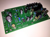
Clearing off a lab bench this morning, I discovered this prototype from last year. I thought some readers might perhaps find it interesting.
It's a motherboard-daughterboard combination. The motherboard has a high gain, low noise amplifier (on the right) with several BNC output jacks, for good signal integrity into an oscilloscope. The daughterboards are early design studies / prototypes of a few different DC-to-DC voltage boosters, as used on the Marauder and Dreadnought front end cards. This fixture is intended to study the supply noise which the boosters do or don't inject onto the higher voltage supply output.
Those big black rectangles are Panasonic polypropylene capacitors, used for AC coupling between the cascaded stages of the amplifier. They create an LF corner frequency around 5 Hz if I recall correctly. Instead of having switchable gain, I simply plopped down separate, individual BNC jacks for +20dB, +40dB, and +60dB of gain. You might be able to see the labels on the silkscreen layer next to the jacks.
And that's how I decided which of the booster candidates, to put on Marauder & Dreadnought.
_
Attachments
My marauder kit arrived today, a mere 20 hours or so from time of order. Thanks so much for putting this buy together and for your excellent customer service! Thanks
@ Tungsten & Mark
Thank you for your kind replies.
I would like to place my front-ends in the same chassis as the F4, and the fact that the layout is made to fit the UMS-heatsinks is a huge bonus to me.
We're closing in on winter, and the long and dark nights, so I might actually have a go at trying to make a layout of the original M2 frontend.
What is the preferred/go-to software to use for layout?
Many many years ago I used something called PCB-Express, but I have no idea if that is capable of producing the files needed for a manufacturer to produce the boards!?
It may be possible to stack the VFET style front end cards on top of the F4 PCBs, using standoffs. Or to do a similar trick with front end PCBs of your own design. The front ends don’t need contact with the heatsinks.
Many of those who design their own boards use KiCad. It’s a more full featured PCB layout program than PCB-Express and can output Gerber files to be used by any Fab service. Another option for simple one-off designs is to use Vero boards, or strip protoboards. I have built several M2x style front ends using Veroboards.
Many of those who design their own boards use KiCad. It’s a more full featured PCB layout program than PCB-Express and can output Gerber files to be used by any Fab service. Another option for simple one-off designs is to use Vero boards, or strip protoboards. I have built several M2x style front ends using Veroboards.
Thank you @Tungsten.
I will take a look at KiCad. I sleep better at night using 'proper' PCB's.
😱
I will take a look at KiCad. I sleep better at night using 'proper' PCB's.
😱
I was planning to use the M2X/Yarra format cards as a front end in my amps. They will all run on +-24v or +24v voltage so they will work better for F4 and other amps that use the Pass first watt PS.
To run an F4 power amplifier at maximum volume you need to give it an input signal amplitude of 14.1 volts RMS.
However, most of the M2x/Yarra format cards operate at unity gain: their output signal amplitude is equal to their input signal amplitude. To drive your [ M2x/Yarra + F4 ] power amp to maximum volume, you'll need to give it an input signal of 14.1 volts RMS, which is much greater than most DACs, tuners, phonostages, and preamps can produce.
One reason why people are interested in possibly using VFET front end cards to drive an F4, is because the VFET cards have a gain of 5X, and several of them can be adjusted for even higher gain. Now your DAC/phonostage/etc only needs to output (14.1 / 5) = 2.8 volts RMS, which is usually quite possible.
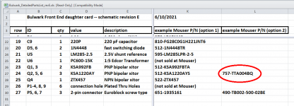
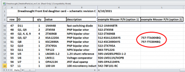
As a general note, the Fairchild / ON Semi KSA1220A has been discontinued by the manufacturer and is currently in Last Shipments status. Mouser shows some expected in April of next year. After that, nada.
Fortunately, at least for now, the Toshiba TTA004B and its complement the TTC004B are still available and seem to be worthy substitutes. Those are what I have been using in my Dreadnought and Bulwark cards.
Fortunately, at least for now, the Toshiba TTA004B and its complement the TTC004B are still available and seem to be worthy substitutes. Those are what I have been using in my Dreadnought and Bulwark cards.
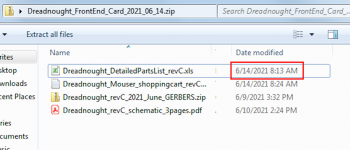
The Toshiba TTA/TTC part numbers have been included in the Detailed Parts Lists as an option / substitute, for months. Always check the Detailed Parts List, always always.
_
_
Attachments

Bulwark and Marauder ordered. I wanted to try with and without transformer options. For an extra $20 I added P089ZB kits to add one per channel.
I wanted to try with and without transformer options
Good on ya! That's the spirit of open minded experimentation. I'm sure you'll have a lot of fun, both building and listening.
I was planning to use the M2X/Yarra format cards as a front end in my amps. They will all run on +-24v or +24v voltage so they will work better for F4 and other amps that use the Pass first watt PS.
M2X/Yarra format daughterboards for Yarra or LuFo are all greater than unity gain. Melbourne and Aksa Lender for example, are 22dB to 29dB gain and some can handle 40Vpp to 55Vpp. The one with OPA454 can do 70Vpp and only needs 12v to 30v input as it has its own on board DCDC booster.
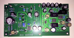
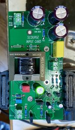
The Scourge boards were the easiest to assemble, aside from the original FE cards that came with the VFET kit. I’m going to let these bake for a while before any serious listening. But there will certainly be some fun listening in the meantime.
Attachments
Um, no, the Unstoppable Beast is member pfarrell, who built two of each front end card from unproven, unverified kits {since he was the verification engineer!}, AND photographed them, AND uploaded it all to the Store website, weeks ago.
He truly is The Man. I'm surprised nobody has asked him "you've listened to them all, which one is BEST?" but having mentioned it, guarantees a quick appearance.
_
He truly is The Man. I'm surprised nobody has asked him "you've listened to them all, which one is BEST?" but having mentioned it, guarantees a quick appearance.
_
- Home
- Amplifiers
- Pass Labs
- Scourge, Bulwark, Marauder, Dreadnought "front end" cards for DIY VFET amp