A diyAudio member has asked
I suspect it is too early to ask or answer this question. People are not yet familiar with Dreadnought, and VERY few people have studied both Dreadnought and MoFo. Certainly I have not -- although I do know Dreadnought, I haven't read any MoFo technical info at all.
I suspect that over time, this may change. Gradually, more and more MoFo experts will have the opportunity and the desire to study Dreadnought. Eventually there might be one or more of them who can answer your question.
However if anybody does have an opinion or an answer today, please reply today!
Hi mark,
Nice work on getting a clean output here with Dreadnought to nearly 19Vrms - congrats:
The MoFo is a 0dB gain output stage and puts out nominally about 11wrms into 8ohms if I recall, so the Dreadnought should be able to drive it comfortably.
I have made a variant of the MoFo with a 36v suppy and 4.75A bias current and gotten 50w out of it. It does need an input stage/preamp capable of 57Vpp or about 20Vrms.
Last edited:
I guess that gives an answer to the question contained in post #112:
It depends on which MoFo you have built. If you built the one that delivers 11 watts output into 8 ohms (thus requiring sqrt(11 * 8) = 9.4V RMS input), then yes, Dreadnought can be used as a front end. Assuming you can figure out a way to provide a 36V DC supply to the Dreadnought card.
On the other hand if you have built the MoFo that delivers 50 watts output into 8 ohms (this requiring sqrt(50 * 8) = 20V RMS input), then no, Dreadnought cannot be used as a front end. You'll need something else, perhaps a brand new design of your own.
could the Dreadnought or Bulwark card be used in the MoFo as a front end -- is it possible given the MoFo topology?
It depends on which MoFo you have built. If you built the one that delivers 11 watts output into 8 ohms (thus requiring sqrt(11 * 8) = 9.4V RMS input), then yes, Dreadnought can be used as a front end. Assuming you can figure out a way to provide a 36V DC supply to the Dreadnought card.
On the other hand if you have built the MoFo that delivers 50 watts output into 8 ohms (this requiring sqrt(50 * 8) = 20V RMS input), then no, Dreadnought cannot be used as a front end. You'll need something else, perhaps a brand new design of your own.
What Mark says is all true, of course.
I would not limit myself only to input stages that will provide full output on your follower stage - MoFo, F4, etc… but rather try them and see if there’s enough output for your typical listening. There most likely will be. The more I do this the more I realize that my normal listening uses only a couple of watts.
I would not limit myself only to input stages that will provide full output on your follower stage - MoFo, F4, etc… but rather try them and see if there’s enough output for your typical listening. There most likely will be. The more I do this the more I realize that my normal listening uses only a couple of watts.

I loaded the mouser cart for dreadnought. I could find alternatives for all backordered items except the KSA1220. Can someone suggest an in-stock substitute?
I strongly recommend using the device types shown on the schematic: KSC2690AY and KSA1220AY. These are the transistors I used in the prototype Dreadnought boards that worked correctly on my lab bench. These are the devices I know will operate correctly.
These KSC/KSA transistors are also used in the M2x removable daughter card "front end" called IPS6. Some IPS6 builders discovered that the KSC/KSA were out of stock, and they made their own personal decision not to wait for the KSC/KSA devices to become re-stocked at Mouser. Instead, these builders decided to substitute the Toshiba TTA004B / TTC004B transistors. The Toshiba parts were, at the time, available and in-stock at Mouser. I have never tried this substitution myself, either in Dreadnought or in IPS6, and I don't have personal experience and knowledge about whether it works acceptably.
These KSC/KSA transistors are also used in the M2x removable daughter card "front end" called IPS6. Some IPS6 builders discovered that the KSC/KSA were out of stock, and they made their own personal decision not to wait for the KSC/KSA devices to become re-stocked at Mouser. Instead, these builders decided to substitute the Toshiba TTA004B / TTC004B transistors. The Toshiba parts were, at the time, available and in-stock at Mouser. I have never tried this substitution myself, either in Dreadnought or in IPS6, and I don't have personal experience and knowledge about whether it works acceptably.
KSA1220AYS
I was successful obtaining some through ebay. This vendor was reliable.
KSA1220AYS 10 New OnSemi transistors sub 2SA327 2SA720 2SA773 2SA777 2SA1220
Regards,
Roy
I was successful obtaining some through ebay. This vendor was reliable.
KSA1220AYS 10 New OnSemi transistors sub 2SA327 2SA720 2SA773 2SA777 2SA1220
Regards,
Roy
Wayne, I was curious to know if you had any success / results with this $30 scope?I have ordered a $30.00 oscilloscope and will see if it can measure a 50K square wave.
Thanks!
Rafa.
I have a question regarding Dreadnought C8. On the schematic pg1 and parts list it says it is a 0.01uF film cap, but on the PCB it looks like it should be an electrolytic (also the picture of a populated example). Can I get some clarification?
It was an electrolytic (>> 10nF) in early revisions. But it measured better and sounded better with a small film cap instead of the electrolytic. Rather than generating an entire new board revision just to change the silkscreen outline shape from circle to rectangle, I left it alone. Stuff a (nonpolar!) film cap and be happy.
The diyaudio store is working on gathering all of the parts necessary to offer kits of these front ends.
Hopefully available sometime this summer!

Hopefully available sometime this summer!
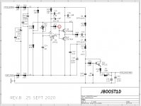
Builders of Marauder and Dreadnought: you'll need to adjust trimmer potentiometer R25 on sheet JBOOST1 / JBOOST1D. I strongly recommend you use an oscilloscope and not a multimeter to perform the setting. You'll be measuring the frequency of a very high voltage AC swing. The AC voltage is too big for lots of meters' "frequency counter" mode, and the frequency is also too high. Please get a correct result on the first try, without damaging your test gear: use a scope.
Set the scope vertical display to 10 volts per division and set the horizontal sweep rate to 20 microseconds per division. Give the trimpot three or four full ANTI CLOCKWISE rotations to start the measurement procedure at a nice low frequency.
Probe the output pin (pin #7) of the LM311 chip. It will be a square wave whose amplitude is 32 to 36 volts. Dial the trimpot R25 to adjust the frequency of this square wave. Your goal is a frequency of 50 kilohertz.
When you get very close to 50 kHz, change the horizontal sweep rate to 5 microseconds per division. You want the square wave PERIOD to be exactly 4 horizontal divisions. Math: 4 x 5us = 20us = (1 / 50000). If your scope happens to be a digital model with frequency measurement capability: use that too.
_
I've finished soldering one dreadnought board. My oscilloscope (Sain DS202) that's served me well for quasimodo, says max 40VDC so a bit close to the expected 36V here. I plan to use the probe on R27 (only option for me as all the other leads were cut too short). For Ground I can use R1 (jumper to ground) correct?
Attachments
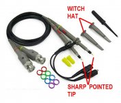
I just pull the witch's-hat off my scope probe, and use the sharp pointed tip to jab into pin 7 of the IC (in its socket). For ground I temporarily install an additional 8 inch long piece of insulated wire, into the PSU Ground hole of the Euroblox connector, and tighten the hold-down screw of the connector. Or if that's too crowded, Dreadnought's Output Euroblox has a ground connection too. When setting the DC-to-DC converter frequency, temporarily yank out the output wires and put your scope ground into the GND Euroblox hole of the Output connector.
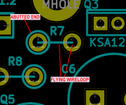
The schematic symbols tell me (and everyone else) which end of a vertically mounted resistor has the flying wirelooop on the PCB layout. Those flying wireloops are also very handy places to connect a scope probe.
_
The schematic symbols tell me (and everyone else) which end of a vertically mounted resistor has the flying wirelooop on the PCB layout. Those flying wireloops are also very handy places to connect a scope probe.
_
Attachments


Last edited:
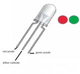
Moderator 6L6 and I have discovered that if you have two Dreadnought boards, each board possessing a switch with two different position settings, then you have 22 = 4 different ways to arrange the pair of switches. You need at least two bicolor LEDs to display all of these possibilities. RR , RG, GR, GG.
Well, at least in my case, I don't see that I will have much desire to mix states. That leaves RR or GG, which can be simplified to R & G from one channel to the front panel, leaving the operator to use observation and confirm that both boards are in sync.
Because off my inattention I ordered too many Dreadnought boards, so I will be giving away 7 pairs free of charge (and free shipping to US locations). PM if you desire a pair.
- Home
- Amplifiers
- Pass Labs
- Scourge, Bulwark, Marauder, Dreadnought "front end" cards for DIY VFET amp