Measure the voltage between pins 8 and 4 of the OPA2134; it's less than the voltage between the pins of the power supply input terminal block connector "P3". Even without the diodes.
Indeed, the voltage drop from the power supply input to the pins of the OPA2134 is greater than I expected it would be. Should be plenty safe for use with the kit SMPS.
I still need to tweak my linear PSU.
I still need to tweak my linear PSU.
Tungsten,
If you still have it out on your bench, what is the voltage across C9 output cap? I see in this post DIY Sony VFET Builders thread
you have a film cap there
If you still have it out on your bench, what is the voltage across C9 output cap? I see in this post DIY Sony VFET Builders thread
you have a film cap there
At this point I am figuring out how to shoe horn the Dreadnought cards into my amp. Looking at the differential amplifier at the heart of the design, one would expect that one end of C9, the output coupling cap, would be at 1/2 of the voltage between POS_BOOSTED and NEG_RAIL. But I haven't measured it. I have only had a couple hours each morning to work before the space starts to approximate the internal environment of the amp when it's been left on for a couple hours.
If you are looking for a recommended voltage rating for C9, I would suggest at least 35V, with 50V being somewhat safer. The film cap I'm using is an Axon 2.7 uF, 250V metalized polypropylene.
If you are looking for a recommended voltage rating for C9, I would suggest at least 35V, with 50V being somewhat safer. The film cap I'm using is an Axon 2.7 uF, 250V metalized polypropylene.
Notes on Dreadnought
I have had the Dreadnought cards playing in my amp for the last few days, with a couple tweaks along the way. These are fairly complex designs, and it has taken me a while to fit them into my home system.
My initial build was fairly close to being "by the book." That is, I increased some power supply capacitors, and used a good 2.7 uF film cap for C9, in keeping with film caps used in the rest of the signal path. I have also wanted a couple dB more gain, so I changed R12 to 22k and decreased R11 to 3.0 k. The horizontal orientation did cause a couple minor issues, so it may be easier for most builders to mount these boards vertically. A set of 15mm standoffs are recommended.
As noted in my description over in the Builders thread, these cards have very good stereo separation, and bass articulation. I also like having just a little more gain. After a couple days, with the circuit not opening up as I expected, I decided to look at C8, the cap which bypasses R15. This part has had a couple values used during circuit development, with the original board layout supporting a 330 uF electrolytic, and the final BOM using a 0.01 uF film cap instead. Notes from the designer suggest that this part plays a role in the sound of the circuit.
Taking a cue from this, I decided to set C8 such that it fully bypasses R15. I substituted the film cap with a Nichicon 1000 uF, 16V aluminum organic polymer. This is one of the caps that I still use and recommend for the ACA. With this value in place R15 is bypassed down to about 1 Hz. This change made an immediate improvement in the dynamic presentation of the amp. The most noticeable changes included a greater sense of presence in percussion instruments. As my old Vandersteens are both time-aligned and phase coherent, proper dynamic presentation makes instruments 'felt' as well as simply heard.
Some additional listening suggested that the new tonal balance could benefit from an adjustment to C26, a bypass for the feedback resistor R12. Increasing the initial value of 4.7 pF to 27 pF showed an improvement. Where the lower value no doubt helps the amplifier circuit maintain stability, higher values may provide some shaping of the overall tone. My ears suggest that 27 pF to 33 pF is a good place to start. The stereo image has been brought forward a little, and micro dynamics are improved. The amp with these values in place has more of the qualities that I have come to appreciate with the overall design.
Until this morning's listening session I was strongly leaning toward increasing C26 even further to 68 pF or even 120 pF. However all seemed right with the CDs that I spun earlier today, so I'm going to hold off on that for the time being. Another possible candidate for tone shaping could be C7. Perhaps a value as high as 100 pF here could tame the output into sounding similar to the Edcor iron. Purely for entertainment purposes, of course.
At this point the Dreadnought cards in my amp offer what I might call a somewhat different, yet equally valid, interpretation compared to the original boards supplied with the kit. Gotta say, it is hard to improve on a JFet buffer + Edcor iron combination, but an alternate interpretation is welcome.
Listen to it with the slide switch in the other position too. Builder's tip: moderator 6L6 likes to put a little piece of high temperature Kapton Tape on the switch actuator, to hold it firmly in his chosen position.
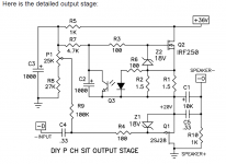
You can trace the signal polarity used in NP's original pair of cards, by studying his 12 page .pdf file. Pay particular attention to the "+D" and "-D" signal interconnect between the FE and the OP card.
Also notice that the P-channel VFET output stage card is inverting, thanks his choice of attachment points for "SPEAKER +" and "SPEAKER -". The N-channel VFET output stage card will be non-inverting (I predict).
_
Attachments
Last edited:
If I were you I would connect the P-channel VFET output stage to the speaker terminals exactly the way Nelson Pass drew it.
Then I would listen to my Dreadnought for a few days with the switch in position_1, and next listen to my Dreadnought for a few more days with the switch in position_2. Then I would put the switch in the position that gave the best sound, and forget all about it. If there was no clear winner, I would put the switch in whichever position lights up the green LED because I like green better than I like red.
If you're burning with curiosity to know WHY he drew it that way, the only person who knows the answer with total certainty is Nelson Pass himself. So you'll need to politely ask him; I think the best thread for that, is probably
DIY Sony VFET pt 1
Notes on Bulwark
The Bulwark cards have been in my VFET amp for a few days already, and I'm very happy with the way they sound. These were easier to build and voice than the Dreadnought cards, having considerably fewer components. There are still a small number of options available, which I did explore a little.
First, I used a pair of 100 uF, 50V Elna Silmic caps at the C2 and C3 locations. While these did take a couple days to break in, I believe they contribute to the excellent overall tonal balance of this front end. I also replaced C7 with a 39 pF film cap, as my experience with the Dreadnought cards indicated film would be preferable to ceramic at this location. I also used a 220 pF film cap at C9 for the sam reason. I initially tried a 1.0 uF polycarbonate cap at C1, then switched back to the 2.2 uF polypropylene recommended in the BOM. The PNP transistors at Q2, Q5 and Q6 are all Toshiba TTA004B.
I played this configuration for a while and enjoyed the way it sounded. Then, I change three parts to boost the gain of the circuit by 3 dB. R22 is now 2.2k, R21 is 4.75k and C10 is a 47 uF, 50V Nichicon ES series. This tweak apparently improved the sound of the circuit more than simply increasing the gain. I have been hearing more detail from the recordings that I am very familiar with. Crispness of percussion instruments was also improved. I can therefore recommend this change even if you don't necessarily feel the need for the extra gain.
We had some discussion in the VFET amp builders thread regarding the secondary termination network on the output of the Edcor. It turns out that this was set by ear, and is open to some personal interpretation. Just for fun, I added a small 220 pF C0G cap in parallel with the film cap at C9. Happily, this didn't change the tonal balance of the circuit, at least to my ears, but it has changed the apparent ease of flow and organic nature of the front end. I recommend this as well. Nothing like an amp that induces one to go back and listen to many recordings that haven't been heard for while.
Good times. 😀

Hi Tungsten,
Thanks for the work you're putting in on these FE boards. I appreciate it. I will be trying some of your dreadnought mods. I have some silver mica in the pF range to use there.
Thanks for the work you're putting in on these FE boards. I appreciate it. I will be trying some of your dreadnought mods. I have some silver mica in the pF range to use there.
Update to Dreadnought
My Dreadnought mods have evolved a little since I last posted them here. They have also been stable for quite a while.
Basically, I ended up replacing all the small ceramic capacitors used for local and global feedback with 47 pF polypropylene film. These are C7, C26 and C27. Yes, the same value of 47 pF in all three locations gave me the smoothest, yet still airy sounding version of this FE. It now shares more of the best qualities of the Bulwark FE. Still a different character, but very subtle. I also added a 0.1 uF polycarbonate film cap in parallel to the 1000 uF cap that I have at C8. This has opened up the transparency slightly.
The same 2.7 uF Axon film cap at C9 for output coupling is there, and what I still recommend for that location. Solen 250V caps from 2.2 uF to 3.3 uF would also work here, but I like the tighter value tolerance of the Axons. Generally speaking, I prefer to use capacitor substitutions that fit fairly easily onto the board. The C9 location can be a tricky fit, depending on the orientation of the boards on the heatsinks.
I had 10 Bulwark PCBs made, and I need only max. four of them. I will therefore give the remaining ones away for free, for the cost of shipping. I guess shipping to EU countries is preferred. Please contact me via pm.
Six cards are gone. No more left. - I will ship them on tomorrow. If everything is ok with the local post office, the shipping rates to the US are low (around $3 letter priority, non insured). I just have to use a very basic and light envelope to stay under 75grams - otherwise the shipping rates will extend $10, which does not make sense.
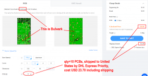
I just accessed JLCPCB.com for a price quote, to fabricate ten Bulwark PCBs and ship them to me in the United States via DHL Express Priority. In my prior experience ordering boards from JLC, this entire build+ship process takes about seven calendar days total, from ordering on the web to receiving the box of PCBs at my front door.
The quoted price was $23.70 for ten boards. Not surprisingly, more than 50% of the total cost was the international express shipping fee. Here's a screen capture image from JLCPCB's website, 15 minutes ago:
_
The quoted price was $23.70 for ten boards. Not surprisingly, more than 50% of the total cost was the international express shipping fee. Here's a screen capture image from JLCPCB's website, 15 minutes ago:
_
Attachments

I had my Bulwark Pcbs made by JLCPCB, but paid even less. Maybe because of using a cheaper shipping possibility.
With the remaining 4 pcbs I will make an alternative for my VFet and a stand-alone preamp, perhaps (without the transformer).
With the remaining 4 pcbs I will make an alternative for my VFet and a stand-alone preamp, perhaps (without the transformer).
Notes on Bulwark w/ Jensen transformer
This modification was introduced in DIY Sony VFET Builders thread
I followed up with my listening impressions today.
After the effort required to get these boards operational, I can highly recommend this configuration for the way it sounds. The Jensen JT-123-FLPCH fits easily into the footprint of the Edcor. The easiest way to complete the wiring was to perform the signal inversion at the secondary windings, rather than at the primary as was done with the Edcor transformer. While I constructed my own mezzanine boards for the conversion, it would be fairly straightforward to modify the Bulwark PCBs to support a dual footprint.
There was a question of whether the Jensen transformers would properly support the signal levels needed to drive the VFET output stage to full volume. I can say that the results so far have been very satisfying to my ears, with the amp driven as loudly as I ever do in my listening room. I haven't looked at the output on a scope yet. It is possible that the smaller Jensen transformers may start to gradually compress the signal as they exceed their rated signal level. However, we already have a proof of concept in the several SissySIT amps by our own ZM that the Jensens can support sufficient signal levels in the autoformer configuration to drive nominal 25W amplifier output stages. So I am not yet too concerned about their application in a 10W amp.
Between the last two variations of the Bulwark FE cards, I can say with some confidence that the p-type NS-10 amp stage sounds very good when it is allowed to provide a few dB of gain. The Jensens seem to have been designed with uniform frequency and phase coherence in mind. With my system, this is just the ticket.
I searched for "Jensen JT-123-FLPCH in Europe" using a popular internet search engine, and this popped up.
[Europe] JT-123-FLPCH Transformers (First Watt F6)
[Europe] JT-123-FLPCH Transformers (First Watt F6)
- Home
- Amplifiers
- Pass Labs
- Scourge, Bulwark, Marauder, Dreadnought "front end" cards for DIY VFET amp