The SPDIF circuit diagram that I posted was
not intended to be a "best" solution for the
NEC 602, and you are right in saying that the
balanced setup is even better.
My problem is that I am not an electrical
engineer or digital signal transmission
wizzard, so I am slowly learning about
all of this. Why don't you guys with more
experience post some good schematic
diagrams of "better" ways to handle
the digital signal from the NEC?
While I am at it, I think that the I2S trans-
mission system is even better than the
balanced RS422 system, if I can believe
what I read.
The bottom line point is that the "stock"
NEC SPDIF output configuration is poor
at best, and the circuit I posted is much
better than that, and easily understood
by others who are also at earlier learning
stages and in need of clear diagrams to
work from.
Fastcat
fastcat95:
Sorry if my question came off harsh, I'm certainly not an expert either and my question was an honest one. I appreciate the schematic, I will probably try implementing something similar in near future. As for the option of a balanced output simply connect the shield of the coax to the "out A-bar" connection of the RS422 instead of ground (A-bar being the A with a bar over the top in the schematic). I'm not sure, buy you might need a 75 Ohm resistor in series with this connection as well for balanced output to stay at the correct impeadence. I'm pretty sure that is all there is to it... somebody please correct me if I'm wrong. Again, thanks for the clear schematic.
Doug - not a digital signal transmission wizard either🙂

Steve:
I am going to post a newer version
of my SPDIF schematic soon that is
a balanced configuration, which is
supposed to be a bit better than
what is now posted.
Fastcat
I am going to post a newer version
of my SPDIF schematic soon that is
a balanced configuration, which is
supposed to be a bit better than
what is now posted.
Fastcat
To all NEC CD-ROM junkies - found an interesting site - it's in Japanese but pretty self explanatory. Me thinks it's an NEC drive that they were working on but not sure. They also list different CD-R's and the digital response of each. Also seem to have a schematic and circuit boards to build a measuringcircuit using LED's for jitter/error sampling is my guess. Anyone who speaks Japanese might be able to give us a rough translation -
ne.jp/asahi/fa/efu/index.html
Toodles, Steve
ne.jp/asahi/fa/efu/index.html
Toodles, Steve
Hey 2A3SET!
Tell us a bit about what you have done with
the NEC CDROM posted here, and what, if any,
mods you have done to the circuits.
Thanks!
Fastcat
Tell us a bit about what you have done with
the NEC CDROM posted here, and what, if any,
mods you have done to the circuits.
Thanks!
Fastcat
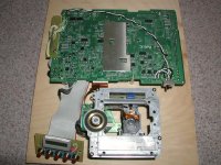
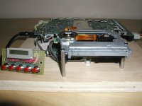
NO mod yet
Just took the transport out as a top loader, connected the LCD to the front. My plan is to load it on a thick aluminum board and construct a case for it.
I am using a DPDT switch to force to read the TOC (P103, P102 104) and will use a relay later.
SLA battery sounds much better than the transformer power supply, and better than NIMH battery.
Will try the TDA1543A directly connecting to CXD2510Q then the Tent XO (I am using LCCLOCK on ROTEL RCD971 with very good result).
Just noticed the Tent XO price has increased as it used to be US$28 including shipping at DIYHIFISUPPLY, and now it's US$35+US$7.
Hi,
Just wondering how things have progressed with the NEC projects. Ive just become interested in using one and hope its still a viable approach.
BTW, I checked the specs of a 401 top loader and they apprear to be similar to the 602. They are missing the PS, analog out, and headphone jack but do have the digital out. Are these going to provide the same performance? Top loading sure is convienient and easier to re-chassis.
thx amt
Hey gang!
Fascinating thread...inspired me to stay up late last night taking apart one of the 602s I have. I'm a newbie to electronics, and a complete alien to digital, but this seems like a simple enough project that it won't require an engineering degree or risk a whole lot of money.
So with that I've got some questions, some (or all) of which may be alarmingly beginner-level, but here goes:
1.) If I were to (successfully) put together the latest (balanced) version of Fastcat's s/pdif circuit, would it work to connect it to the internal digital out, or must it be attached to r819?
2.) If it must be the r819, does anyone have any hints/tips/suggestions on how to solder a wire to (what I think must be) an SMD resistor?
3.) Parts questions. Fastcat calls for a 74vhc04 and a ds9638. LeoJar calls for a 74uhc04 and then to 75176. Are these parts interchangable?
4.) More parts questions. I know I can get all of these chips at Digikey or Mouser or whatever, but Jameco is right down the street from my house and I can get stuff there without a minimum order. They don't have the 74vhc04, but they do carry a 74hc04 and a 7404. Will these work?
5.) Still more parts questions. What kind of caps are those on the Fastcat schematic (ceramic, film, electrolytic)? Does it matter?
6.) Grounding questions. The unused inputs on the 74vhc04 and pin 4 of the ds9638 go to digital ground. What about the 2 ground points after the caps near the +5vdc...is that digital ground as well, or the 5vdc power ground?
7.) For digital ground, can I simply wire it back to the pin labeled "ground" on the internal digital out of the NEC?
8.) Has anybody built this? Does it noticably improve the sound of the digital out?
Thanks so much!
Hello!
1.) The digital out socket from the internal NEC drive leads to
R819 on the main drive ckt. board. The digital out socket is
simply the digital out and ground connection
3.) As for the parts (74vhc04 and a ds9638; 74uhc04 and 75176),
either should work OK, but worth it to check data sheets.
But, I have heard that that the DS9638 output connections
used ( A and A not) may create a problem because of a
propogation delay between A and A not. Might be better
to use just the A out from the 9638 chip, and connect the
BNC output jack ground lug straight the NEC power supply
ground. Of cource this is not balanced. I tried some time
ago to get Leo jar to comment about all this, but no response.
4.) 74hc04 is OK, but not familiar with 7404.
5.) Caps: chip bypasses (0.1 uF) on NEC side of schemtic are
ceramic multi-layer. Forget the 47pF cap across
the SPDIF input at the DAC; the 0.047uF caps
feeding the CS8412 could be something like
Wima polypropolene with perhaps 1 nF COG
multilayer ceramic bypasses.
6.) The ground returns for the 0.1 uF caps should go back to
the power supply ground, preferably very low inductance
seperate return lines if possible.
7.) This ground on the NEC simply connects ultimately to the power
supply ground of the NEC drive.
8.) Has anybody built this? Does it noticably improve the sound of the digital out?
The idea of the NEC output circuit was to create a buffer for the
raw digital TTL signal from the digital NEC drive output connector
and to be sure that the final output was a true 75 ohm type
with a 75 ohm BNC output jack. All of this should be able to
clean up the wave shape of the digital signal from the NEC
( I assume that you have seen the scope photo from Leo's
web site on the NEC drive) and create a better SPDIF
transfer with the impedances correctly matched (75ohm)
Hope all this helps you out. I have not yet built the circuit for my
NEC 602, but do believe that it will improve the sound if properly
configured and carefully built.
Fastcat
Not directly...after R819 the signal goes through Q309 (a 2sc2412), R341, and does some kind of loop with ground that I don't understand before reaching the digital out socket...see page 5 of the schematics.fastcat95 said:1.) The digital out socket from the internal NEC drive leads to
R819 on the main drive ckt. board. The digital out socket is
simply the digital out and ground connection
Anyway, it's good news that your circuit is designed to use the NEC output connector...by your schematic I thought it was necessary to bypass that last little bit of the circuit. You might change R819 on your schematic to DOUT, or P303, or whatever is appropriate.
I looked at the data sheets, and I didn't see anything glaringly obvious that was different about them, but then 95% of the stuff in data sheets flies well over my head.fastcat95 said:3.) As for the parts (74vhc04 and a ds9638; 74uhc04 and 75176),
either should work OK, but worth it to check data sheets.
Um, okay. Balanced is better, right? What do you think of the circuit proposed in this thread:fastcat95 said:But, I have heard that that the DS9638 output connections
used ( A and A not) may create a problem because of a
propogation delay between A and A not. Might be better
to use just the A out from the 9638 chip, and connect the
BNC output jack ground lug straight the NEC power supply
ground. Of cource this is not balanced. I tried some time
ago to get Leo jar to comment about all this, but no response.
http://www4.head-fi.org/forums/showthread.php?t=54211&page=2&pp=20#postmenu_645267
...uses a 74act14 and a Newava s22083 instead...are these the same types of chips? Someone posts a comment about the need to decouple the IC.
There's a pin labeled 'ground' on the digital out that I assume goes to digital ground, and a pin labeled 'ground' on the power socket that I assume goes to power supply ground. Is that not the case?fastcat95 said:7.) This ground on the NEC simply connects ultimately to the power
supply ground of the NEC drive.
I have seen it...makes quite a compelling argument, even though I don't know exactly what the 'scope is telling us here.fastcat95 said:The idea of the NEC output circuit was to create a buffer for the
raw digital TTL signal from the digital NEC drive output connector
and to be sure that the final output was a true 75 ohm type
with a 75 ohm BNC output jack. All of this should be able to
clean up the wave shape of the digital signal from the NEC
( I assume that you have seen the scope photo from Leo's
web site on the NEC drive) and create a better SPDIF
transfer with the impedances correctly matched (75ohm)
It definitely helps a lot. I'm pretty confident that I can put it together so it'll work well enough to at least pass a signal, tho I'm not so sure about 'properly configured' and 'carefully built'! I actually have 4 of these drives, unmodded, so I'll have plenty of opportunity to A/B test with a stock drive.fastcat95 said:Hope all this helps you out. I have not yet built the circuit for my
NEC 602, but do believe that it will improve the sound if properly
configured and carefully built.
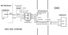
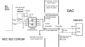
To All:
I am reposting the latest version of my SPDIF upgrade
schematic for the NEC 602 CDROM drive. This schematic
has some updates that reflect new information about
some of the component particulars.
This circuit is not the ultimate, but will work much better
that the origonal NEC output circuit, and all the parts are
easy to obtain in small quantities. A few notes:
Either the A or the A not output can be used from the
DS9638 RS-422 chip. Note the impedance notices.
A seperate ground line is used for the output BNC jack
to the NEC power supply ground origin.
At the recieving end, the 75 ohm resistor should be
placed as close to the input BNC jack as possible, and
the input should be as close to "resistive" as possible.
The 0.047uF series capacitors between the input and
the CS8412/14 will form a DC block, and also help with
the issue of having the grounds between the NEC and
the DAC connected (ground loops).
Thanks to all who have contributed to this thread so far!
Fastcat
Attachments
Hello!
A quick follow up to my re-posted SPDIF
schematic. The output level of my circuit
is decidedly higher than the standard 0.5
volt SPDIF spec/. This seems to work well
with the Crystal CS8412/14, but might not
with another type of input reciever. In that
case a voltage divider with a resulting 75
ohm impedance will pad the level down to
the spec. level.
Fastcat
Possible to replace LCD with larger type?
Has anybody tried to replace the small LCD on the Multispin 6x or 4X with a larger type of display?
If so, I would be grateful to know what type of replacement you used and what modifications were needed.
It would be good to know whether such a modification is even possible or feasible.
I am using 4X multispin which is top loading. The boards are very similar to the 6X CDR.
Cheers
Joe
How about crystal replacements? Can anyone make a recommendation for a better crystal on the CD-602? I see some comments about replacing the 33mhz one at the beginning of this thread, but I'm a newbie to some of this digital stuff, and have no idea where to locate a better crystal at (I don't want to jump head first into a guido/elso clock yet...).
Thanks!
Thanks!
Hello!
If you can find crystals that match the needed
frequencies, and if they have VERY, VERY LOW ppm
frequency drift, that might make an improvement.
Otherwise, try putting some damping material
on all the crystal cans, and of course a better
and lower noise power supply always helps.
Fastcat
If you can find crystals that match the needed
frequencies, and if they have VERY, VERY LOW ppm
frequency drift, that might make an improvement.
Otherwise, try putting some damping material
on all the crystal cans, and of course a better
and lower noise power supply always helps.
Fastcat
- Status
- Not open for further replies.
- Home
- Source & Line
- Digital Source
- Schematics for NEC 602 CDROM Drive?