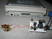
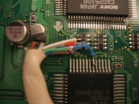
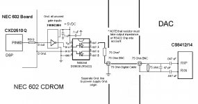
Finally, an internal view of where the dig lines were intercepted for the sony format to the TDA1543A. The two clock and data lines were taken from a resistor pack near the CXD2510. The "twisted pair" mates for the CAT5 wire were taken to ground found on the adjacent chip.
Power right now is provided by a small switching power supply, soon to be batteries when I find the time.
Works well so far!
Power right now is provided by a small switching power supply, soon to be batteries when I find the time.
Works well so far!
Attachments
CXD2510Q data sheet in English
CXd2510Q data sheet in English
I have the CXD2510Q data sheet in English (see post 21). I will email to anyone interested for their own use, or to post on their WEB site.
Gary
CXd2510Q data sheet in English
I have the CXD2510Q data sheet in English (see post 21). I will email to anyone interested for their own use, or to post on their WEB site.
Gary
Excellent work!!!
Thanks for your efforts!!!
I saw this posted on another thread:
Originally posted by Kuei Yang Wang
Konnichiwa,
The input driver CAN make a serious improvement, as can be using a TTL Level "direct" output in S/P-DIF format to the CS8412/14 inputs.
Here is why. The Cirrus Logic Receivers are optimised to operate using Pro-Level interfaces. That means 3...10V P-P or a push-pull TTL output. Conventional S/P-DIF is standardised as 0.5V P-P or in other words 20db lower. No matter how good the triggering of the Inputs is, having a signal level around 20db below that apropriate to the interface as designed will mean the jitter performace is compromised.
BTW, the 47Labs transport has two interface options (AFAIK), one 5V PP via the "DC" output, the other conforming to S/p-DIF according to spec. Guess which one sounds better?
I have asked if this means you can run the 5V TTL out of the back of the 602 into the 8412 without damaging it - I'll report my findings.
Unless, of course, you don't need a digital receiver.....! 😉
Cheers
Jon
Jon, the dig out portion of the schematic is on this page.
http://www.audioworkshop.com.hk/photo/5 Audio.jpg
It's pretty simple, and I'm sure you can easily intercept the signal at the CXD2510.
I don't see the advantage in doing so, unless you are trying to use an existing DAC or a non-sony format DAC. Its a lot less work and less complication to bypass the receiver altogether unless you need it for the reasons I just mentioned. Even if you were trying to use a I2S dac, I believe info has been posted on this thread for the glue logic required to convert sony format to I2S. I haven't tried the DAC with a receiver to compare the differences between receiver and no receiver, but I believe the consensus and theory is in favor of no receiver if you can get away with it.
One possible advantage of using an input receiver is if you wish to reclock the data using one of the aftermarket clocks. There's plenty of data and schematics on how to reclock the CS8412/TDA1543 combination, but I'm not sure if this can be directly applied to the CXD2510/TDA1543A interface. If anyone has ideas on how to implement reclocking while using the Sony interface to the dac, I'd be willing to test it out and report on the results.
Norm
Norman-
While I'm certainly not an expert, most of the schematics for reclocking the CS8412/TDA1543 do the reclocking after the 8412, ie on the same clock lines that come off of the CXD2510. Take a look at the bottom schematic in this post for one implementation:
http://www.diyaudio.com/forums/showthread.php?s=&threadid=28879
It seems like this is independent of the reciever chip and should still work...but of course I don't really know what I'm talking about when it comes to digital circuit design...🙄
Doug
Jon:
With regards to the better sound provided
when a higher Peak to Peak digital signal is
sent to the CS8412; assuming this is true,
would the following be possible:
1. Take output of NEC 602 and route it
through an RS422 line driver chip to
get a buffer and output drive capability.
2. On the non inverting output of the RS422
driver chip, add a series 75 ohm resistor
to make the SPDIF impedance specification.
3. Route the signal to a 75 ohm BNC jack at
the back of the 602 unit.
4. Connect the SPDIF (higher level signal) with
75 ohm coax/ BNC connectors to DAC with
CS8412 reciever.
Now the CS8412 would have a higher level input
digital signal, and still meet the SPDIF impedance
specification.
Any comments on this approach?
Fastcat
TTL
Thanks for all the comments.
I'll have a look into this over the next week or so. My digital circuit knowledge is poor, but I was wondering if you could just attach the 5V TTL to the BNC with a 75R series resistor.......
More digging required from me, I think! 🙂
Cheers
Jon
Thanks for all the comments.
I'll have a look into this over the next week or so. My digital circuit knowledge is poor, but I was wondering if you could just attach the 5V TTL to the BNC with a 75R series resistor.......
More digging required from me, I think! 🙂
Cheers
Jon
Jon:
The TTL signal seems to be comming directly
out of the Sony chip.
I have seem scope photos of this signal, and it
seems to be a bit "dirty" and mis-shaped. I think
this is why people use some sort of buffer to clean
up the digital signal, and provide drive capability
for the SPDIF output. Usually a 74HCU04 chip and
something like an RS422 transmitted chip. Others
have paralleled the 74HCU gates and used the resistor
divider, although some say that the paralled gates
increase jitter.
Fastcat
Fastcat,
Yes, pin 60 of the sony chip is Dout. I sketched out the schematic more or less on page 2 of this thread. I checked it with the actual schematic and its correct.
You mentioned a "dirty" signal. If the signal coming from the chip directly is dirty, and I'm using the sony format clock and data lines from the same chip, wonder if cleaning those up will help there as well. I'm interested in the schematic you'll be using to square up and clean up the ttl signal 😀
Norman
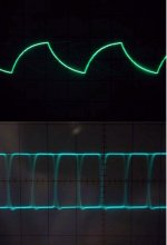
The digital signal out of the NEC (Sony chip) is
"dirty" in the sense that it is not a clean data
stream with a sharp, clearly formed digital pattern.
It could be that the output resistors, and / or
inductors play a role here. I have seen scope
photos that show a much improved data stream
appearance after a buffer circuit is substituted for
the origonal scheme on the output. As to the idea
that the sould will improve with the data stream
cleanup, I am not totally sure about that. The other
data lines from the Sony chip might be cleaner,
depending on how they are connected or loaded,
etc. It is also impossible to be sure how much
loading the pin 60 D out of the Sony chip can tolerate.
This is one reason why people put a buffer between
the chip and the output jack. It would be nice to just
add a series 75 ohm resistor and run straight to the jack
if performance did not suffer. Anyone have an O'scope
that will allow them to check this out?
I will post a few drawings here shortly with several
circuits that I think will work well for an output buffer.Fastcat
Fastcat, et al ...
Seems there been a tremendous amount of progress on the NEC!! I've been lollygagging at AAsylum for about a year. Bless you all for getting the schematics - WELL DONE!!!
I picked up 4 of these drives about 2 years ago, gave one away, kept 2 as back up and tore into one. Ripped out the entire mess at the rear of the drive. Added an overkill power supply, did the caps and damping. I've got the digital out at the back of the drive going to an Alchemy DTI then to a modded DDE 3.0.
The question is - Have you noticed a great deal of difference changing the digital out? If you have, then kindly explain the best circuit for the changeover. I've read the posts and the more I read - the more cornfused I get.
I don't know if anybody has done this here but I posted on AA a while back on the use of a light lubricating oil on the spinner in the top of the caddy. They slip out if your careful - apply a LIGHT film of oil to the aluminum cap and slip the disc back in. Also painted the inside of the caddy flat black. Both tricks helped. I've amassed about 75 caddies - I think I've got enough for a while.
Steve 😕
Oh...Yes
These are the images from my website.....
http://www.geocities.com/leojar2002/Cd_4x_top.html.
Using the RS422 standard chip is the best way to reform the signal.
leo
These are the images from my website.....
http://www.geocities.com/leojar2002/Cd_4x_top.html.
Using the RS422 standard chip is the best way to reform the signal.
leo
Leo:
Could you post a schematic of the logic/RS422
output circuit that you used in your NEC for
the SPDIF? Also, has anyone experimented
with using a HQ optical interface and cable
to transfer the digital signal to a DAC?
____________________________________________
Here is a list of potiential mods for the NEC CDROM:
____________________________________________
Low impedance/low noise +5 & +12 VDC power supplies
Improved SPDIF output interface circuits
(both standard and optical)
Better audio / SPDIF output jack(s)
Damping of circuit crystals (and/or replacing with better units)
Replacing / upgrading critical clock circuits
Improved chip P.S. decoupling where possible
Better electrolytics on circuit board where possible
Damping of interior structural components, case, etc.
Better isolation system for outer case
Improved cooling flow inside case
Painting inside of caddy flat black or green
Oiling the caddy aluminum spindle cover area
___________________________________________
Please feel free to post ideas/ schematics / photos!!!
Fastcat
I am using SN75176 and you can go to the below link and chk the standard configuration. It is easy and only one resistor and one good powersupply.
http://focus.ti.com/lit/an/slla070c/slla070c.pdf
The signal from 602 will go to 74uhc04 and then to 75176.
RS422 is a balanced signal transfer method and the noise immuse ability is very high. What I was doing is to make sure the signal-out from the cd rom is equal to the signal-in in DAC.
Easy to build..
Leo
Is there a reason you aren't using the balanced output of the RS422 chip? I know the CS8412 has a differential input...
Doug
Doug
As dcole said, CS8412/4 has the standard rs422 receiver. So, it is better using balanced out from the chips.
- Status
- Not open for further replies.
- Home
- Source & Line
- Digital Source
- Schematics for NEC 602 CDROM Drive?