Thanks for the reply. I plan on swapping the switching PSU for a pair of regulated supplies built on Digi01's generic regulator PCB. Probably LM317's or LT1084's with a beefy cap-bank before the regulator.
The reason I asked about the crystals was I took a peek at Digikey's crystal selection and I don't even know where to begin. I haven't stripped my drive yet, so I was hoping someone on here who had swapped their xtal for a better one could make a recommendation. If nobody's done this (or those that have no longer post here), I'll probably have to disassemble the drive to get the right size/value and then poke around for a better one.
The reason I asked about the crystals was I took a peek at Digikey's crystal selection and I don't even know where to begin. I haven't stripped my drive yet, so I was hoping someone on here who had swapped their xtal for a better one could make a recommendation. If nobody's done this (or those that have no longer post here), I'll probably have to disassemble the drive to get the right size/value and then poke around for a better one.
Parts so far
I'm making a larger order from Mouser, so I'm trying to throw in the parts for this thing. Here's what I've found so far, please review and let me know if these are okay:
74VHC04B
ST 5V Logic (HCF4xxx, M74HC/HCT, 74AC/ACT, 74VHC/VHCT)
DIP-14 Hex Inverter
Mouser part #: 511-74VHC04B
$0.36
21RX310
Xicon Epoxy Dipped Multi-Layer Ceramic Capacitors
CAP 50V .1uF X7R
Mouser part #: 21RX310
$0.38 ea. (need 2)
Mouser doesn't stock any dip-8 rs422 chips. On to Digikey (who doesn't stock any dip-14 hex inverters):
DS9638CN
IC DRIVER DUAL HS DIFF 8-DIP
Digikey part #: DS9638CN-ND
$1.65
Plus hook-up wire and a little protoboard.
Its stupid to pay multiple shipping and minimum order charges for what amounts to less than $3 in parts, so extra bonus points to anyone who can find everything from a single vendor!
I'm going to be using this with a variety of DACs, so I'm not comfortable having the signal voltage out of spec (i.e. anything other than .5v). What would I use for "a voltage divider with a resulting 75 ohm impedance"? How do we calculate the proper impedance with the ds9638?
To All:
Someone on this NEC thread posted a link to a set
of schematics that would give the frequencies for
the crystals used. If you cannot access the link,
I can post the crystal frequencies, or try to E-mail
the schematic sheets with them shown.
As to the output voltage divider for use with my
circuit using the DS9638 RS422 chip, let me check
on that, and I will try to post a simple drawing
showing a way to get the output voltage down
to the 0.5 volt SPDIF spec, and maintain the 75 ohm
output impedance. There are only 2 resistors
involved in doing this. BTW, the output impedances
that I showed for this chip in my last schematic
update came from an inquiry response from National
Semiconductor.
Fastcat
To All:
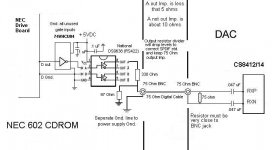
I am posting a modified version of my SPDIF output
circuit that reduces the output level to the SPDIF
standard 0.5 volt, and also keeps the proper 75 ohm
output impedance.
As always, if anyone is doing NEC mods, please post your
results and pics if possible!
Thanks to all contributors!
Fastcat
I am posting a modified version of my SPDIF output
circuit that reduces the output level to the SPDIF
standard 0.5 volt, and also keeps the proper 75 ohm
output impedance.
As always, if anyone is doing NEC mods, please post your
results and pics if possible!
Thanks to all contributors!
Fastcat
Attachments
Awesome, Fastcat, thanks!
We're getting closer...are those resistors? Any particular type? There's over 300 97 ohm parts on Mouser, and over 1000 330 ohm. Are we looking for anything in particular here?
We're getting closer...are those resistors? Any particular type? There's over 300 97 ohm parts on Mouser, and over 1000 330 ohm. Are we looking for anything in particular here?
Audionewb:
On the resistors, I would suggest at
least 1% accuracy metal film types
with a 1/4 watt rating. Mouser has
some very nice Vishay units in their
catalog.
Also, if you will be feeding a DAC that
does not have a series capacitor in
the SPDIF signal line to the reciever chip,
I would suggest having a 0.1 or 0.047 uF
HQ Wima polypropolyne capacitor before
the 330 ohm resistor. Also at Mouser.
Fastcat
<< Also, if you will be feeding a DAC that
does not have a series capacitor in
the SPDIF signal line to the reciever chip,
I would suggest having a 0.1 or 0.047 uF
HQ Wima polypropolyne capacitor before
the 330 ohm resistor. >>
Sounds good. Is there any harm in having a cap before the 330 ohm resistor if the DAC does have a series capacitor in the spdif signal line?
>Sounds good. Is there any harm in having a cap before the 330
>ohm resistor if the DAC does have a series capacitor in the spdif >signal line?
This should not be a problem. One of the things that I like
about the schematic I posted is the fact that the CS8412/14
chip has caps on both the RXP and RXN pins, which should
provide a form of blocking to lower frequency AC or DC that
might otherwise couple between the transport and the DAC,
particularly through the ground connection between the 2
units. This is where a pair of excellent, and properly
implimented, digital pulse transformers would be best if
you knew where to get them and how to design them
into the circuit. An elimination of "hardwire" connection
between transport and DAC.
Fastcat
Fastcat circuit on protoboard
I've attached a mockup of the Fastcat circuit on Radio Shack protoboard (#276-150). I've never done anything like this before, so I'm just trying to get as much feedback as possible before firing up my soldering iron.
Do you see any mistakes or obvious inefficiencies? Anyway I could lay this out without requiring so many jumpers?
Thanks for your help!
Another one...
This is fun! Kind of like solving a little puzzle. This one is much easier, as long as there's no problem running the ground trace beneath the ICs. You'd still need to ground the ICs, but I left the jumpers/blobs of solder off the diagram to keep it simple.
Let me know what you think!
This is fun! Kind of like solving a little puzzle. This one is much easier, as long as there's no problem running the ground trace beneath the ICs. You'd still need to ground the ICs, but I left the jumpers/blobs of solder off the diagram to keep it simple.
Let me know what you think!
Hello!
Your second circuit layout looks a bit
more streamlined...
A few thoughts:
The 0.1 uf bypass capacitors for the chips
should (ideally) go directly between the
+5 pins and the GND pins. Axial multi layer
ceramic types are very good for this due to
their very low high frequency impedance.
Some people go further and use leaded
ferrite beads from the +5 source to the
+5 pins of each chip for more filtering of
very high frequencies. It is also possible
that adding a very low impedance 47 to
100 uF electrolytic to the board where
the +5 first enters would also help with
power supply noise. Be sure that ALL
unused logic gate inputs in the 74' chip
are grounded (outputs can be left open),
as well as the input to the unused DS9638
amplifier circuit.
Keep us posted on your progress!
Fastcat
I don't understand this. Do you mean one end of the cap sticks in the same hole as the +5 pin on the chip, and the other end sticks in one of the holes shared by a grounded pin? Or do you mean they should just mount as closely as possible to the +5 pins? Double stuffing PCB holes is a pain.fastcat95 said:The 0.1 uf bypass capacitors for the chips
should (ideally) go directly between the
+5 pins and the GND pins. Axial multi layer
ceramic types are very good for this due to
their very low high frequency impedance.
I don't actually know what ferrite beads are, but I've heard this before. I figured they could just replace the jumpers on my diagram where appropriate. Again, looks like there's lots of different kinds, with different ohm & MHz values. What kind am I looking for?Some people go further and use leaded
ferrite beads from the +5 source to the
+5 pins of each chip for more filtering of
very high frequencies.
No problem, that's easy.It is also possible
that adding a very low impedance 47 to
100 uF electrolytic to the board where
the +5 first enters would also help with
power supply noise.
Yup. They are on my first diagram (pins 1, 3, 5, 7, 9, 11, 13 on the 70xx04, and pins 3 & 4 on the DS9638). It would have made my 2nd version diagram too messy, but since the ground plane is so close to the ICs, they can be connected easily with a little blob of solder.Be sure that ALL
unused logic gate inputs in the 74' chip
are grounded (outputs can be left open),
as well as the input to the unused DS9638
amplifier circuit.
You bet!Keep us posted on your progress!
As to the 0.1 uf caps and the chip pins...
you could solder the caps between the +5
pin and the GND pin on the back of the board
where the chip pins stick through. There are
also commercial chip sockets that have the
capacitor directly connected between the
appropriate pins, all within the chip socket.
(at least for the 74' chip )
Anyway the idea is to get the shortest, and
most direct bypass connection between +5 and
GND of each chip.
As to the ferrite beads on leads, it is probably
not too critical as to the type, and they could
replace the jumpers, if the jumpers are leading to
the +5 pin of each chip.
As far as electrolytics, the Panasonic FC or FM
series are both good for this application.
What are you using for a +5 power supply here?
Fastcat
Okay, that doesn't sound too tough. Keep an eye open for those sockets with the built-in caps for me, tho, will 'ya? That sounds pretty cool.fastcat95 said:As to the 0.1 uf caps and the chip pins...
you could solder the caps between the +5
pin and the GND pin on the back of the board
where the chip pins stick through. There are
also commercial chip sockets that have the
capacitor directly connected between the
appropriate pins, all within the chip socket.
(at least for the 74' chip )
For now, I was just going to take a splice off the existing 5v line going in to the CD-ROM. Once I get the digital output cleaned up I'll start working on moving the power supply out of the box, and probably go with something like this, or like this, or maybe even like this.What are you using for a +5 power supply here?
Hello!
At mouser.com -
14 pin gold socket with 0.1 uf ceramic bypass
# 575-413314 $ 1.65
Fair Rite EMI leaded beads for broad band rejection
# 623-2743001112
The chip socket is a good thing, and gives you the
easy option of replacing the 74' if it should somehow
get zapped with ESD, or something. The beads listed
above are small and an easy fit. Since you will be using
the OEM +5 VDC to power at first, the use of the very
low impedance electrolytic is a very good idea. There
is a lot of switching noise in the NEC power supply.
Mouser also has Nichicon electrolytics with very low
impedance and small size in their catalog.
Post a photo of the board when you finish it!
Fastcat
Okay, here's the final layout and parts list. I've got questions about a couple of parts, where they were out of exactly what I was looking for. I assume the substitutions will be fine, but better safe than sorry.
1. 74HC04 mounted on:
Mill-Max Capacitor Sockets
14P GLD PIN GLD CONT
#575-413314
2. Any thoughts on which of these would work better, 100uF or 47uF? I wasn't sure if the 25v rating would matter, but it was the only Nichicon Electrolytic in 47uF. If it doesn't matter, I'll pick the cheaper one and save $0.16:
Nichicon Low Impedance Aluminum Electrolytic Capacitors - 105 Degree
10V 100uF
#647-UHE1A101MDD
Nichicon UPW Low Impedance Radial Aluminum Electrolytic Capacitors - 105Degree
25V 47uF 5x11
#647-UPW1E470MDH
3. Kemet Conformally Coated Axial Ceramic Capacitors
50V X7R .1uF 5%
#80-C412C104J5R
4. Is 1/2 watt okay for this?
Vishay/Dale 1/2WATT Metal Film Resistors
1/2WATT 97.6KOHMS 1%
#71-RN65D-F-97.6K
5. Is 1/2 watt okay for this? How about .1% rating? I figured that made this a seriously robust resistor...it certainly has a seriously robust price ($1.38 ea.!)
Vishay/Dale 1/2WATT Metal Film Resistors
1/4WATT 330OHMS 0.1% 25PPM
#71-RN65E-B-330
6. Wima Polypropylene Film Capacitors
100V .1uF 5%
#505-MKP20.1/100/5
7. Fair-Rite EMI Shield Beads on Leads
LF Z=68 OHM @ 100MHz
#623-2743001112LF
If these all look okay, I'll go ahead and drop the order this weekend!
Hello!
1. OK
2. Nichicon 56uf / 50 volt UHE 647-UHE1H560MED
3. OK
4. ¼ watt 1% is fine
5. ¼ watt 1% is fine
6. OK
7. OK
On your board diagram, 2 things-
Capacitor # 2 (56uf electro) is shown in series leading to the chips.
It should actually be between the +5 VDC entry point and the GND
with the + capacitor terminal on the +5VDC. Assuming that the D
GND wire in your picture is the one going back to the 2 wire jack
at the back of the CDROM drive, I would leave that wire as it is,
and run a separate GND wire from the power supply output to the
pads just below the +5 VDC entry point. Then put the electro cap.
across the +5VDC entry point and the new GND wire just below
it. That way any power drawn by the chips will travel through the
new ground wire, rather than taking the path through the D out
signal jack GND wire from the drive. After the 56uf cap., run this
new GND wire onward to the GND buss that the D GND is
connected to. The ground for the power supply output is
common to both the +5 and +12 VDC, and you will notice
that the p.s. output wire harness has (2) black GND wires in
addition to the red and yellow.
Try posting a revised picture. You are almost there.
Fastcat
fastcat95 said:Hello!
1. OK
2. Nichicon 56uf / 50 volt UHE 647-UHE1H560MED
3. OK
4. ¼ watt 1% is fine
5. ¼ watt 1% is fine
6. OK
7. OK
Great, thanks! On the resistors, Mouser doesn't stock ¼ watt 1% Vishay/Dales in 330 and 97 ohm right now. If 1/2 watt .1% is okay (an unneccesary upgrade?) I can stick with Vishays, or I'll have to switch to a different brand.
Here's the updated circuit. Getting a little crowded in the 'power section', hopefully its clear enough. Is this what you had in mind? Also, does polarity matter for the other two caps?
AudioNewb:
Use what resistors you want if the 1/4 watts are not available.
The circuit looks good ( I assume that the jumper between the
2 chips will be on the underside, or routed such that there is
not a very close passing of the jumper to other components),
and only the polarity of the 56uf electro cap is important. The
output cap and the ceramic bypasses have no polarity.
Fastcat
Okay, then, we're off and rolling! Here's the final parts list in case anybody else is interested:
1. Mouser part #: 575-413314
110-13-314-41-801000
Mill-Max Capacitor Sockets
14P GLD PIN GLD CONT
2. Mouser part #: 647-UHE1H560MED
UHE1H560MED
Nichicon Low Impedance Aluminum Electrolytic Capacitors - 105 Degree
50V 56uF 6.3X11
3. Mouser part #: 80-C412C104J5R
C412C104J5R5CA
Kemet Conformally Coated Axial Ceramic Capacitors
50V X7R .1uF 5%
4. Mouser part #: 271-97.6
271-97.6
Xicon 1/4W 1% Metal Film Resistors
1/4WATT 97.6OHMS 1% 50PPM
5. Mouser part #: 271-330
271-330
Xicon 1/4W 1% Metal Film Resistors
1/4WATT 330OHMS 1% 50PPM
6. Mouser part #: 505-MKP20.1/100/5
MKP2-.1/100/5
Wima Polypropylene Film Capacitors
100V .1uF 5%
7. Mouser part #: 623-2743001112LF
2743001112
Fair-Rite EMI Shield Beads on Leads
LF Z=68 OHM @ 100MHz
Mouser part #: 511-74VHC04B
74VHC04B
ST 5V Logic (HCF4xxx, M74HC/HCT, 74AC/ACT, 74VHC/VHCT)
DIP-14 Hex Inverter
Digikey part #: DS9638CN-ND
DS9638CN
IC DRIVER DUAL HS DIFF 8-DIP
Radio Shack part #: 276-150
Multipurpose PC Board
All the parts to build two of these things should be well under $20. I'll post a photo when I'm done!
- Status
- Not open for further replies.
- Home
- Source & Line
- Digital Source
- Schematics for NEC 602 CDROM Drive?