Thank you for providing the UNICO 100 SERVICE MANUAL. It has been of great help to me.
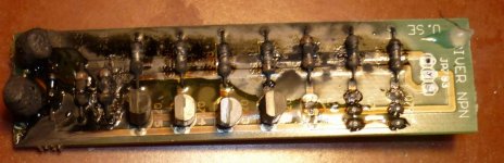
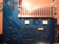
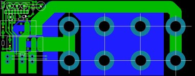
This looks very bad. You should replicate the board.
Or is it possible to clean it ?
The brand of resistors is not important.
I will have a look for a spare board if necessary.
Or is it possible to clean it ?
The brand of resistors is not important.
I will have a look for a spare board if necessary.

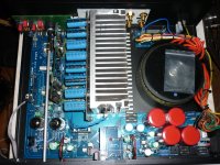
Unico SE
This is a factory solution ? Or somebody made it? Is 7W necessary? Because it would be a more professional solution with KOA resistors.
https://hu.mouser.com/ProductDetail/KOA-Speer/BPR58CR27J?qs=1He0yLMpldCMYYGdCb71yg==
This is a factory solution ? Or somebody made it? Is 7W necessary? Because it would be a more professional solution with KOA resistors.
https://hu.mouser.com/ProductDetail/KOA-Speer/BPR58CR27J?qs=1He0yLMpldCMYYGdCb71yg==
Attachments
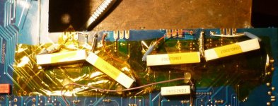
Obviously these emitter/source resistors are not original.
Have a look for the three leg double types or replace with
smaller resistors which fit the available space.
Have a look for the three leg double types or replace with
smaller resistors which fit the available space.
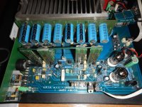
I have a problem with Unico SE. Right channel has about -50V at the output.
Nothing is burnt, BF421 x 7pcs on the vertical board are quite hot because of this, but everything seems to be OK. Supply voltages are OK. Transistors, diodes, and "important" components seem to be OK.
I swapped parts between channels: tubes, bias boards, and disconnected power to MOSFETs - no result, something is wrong with the main board on the preamp/driver side. As far as I remember, I also disconnected the bias boards.
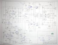
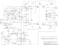
Here are two schematics with measured voltages. Pin 2 on JP19/JP24 should be 0V, but there is 3.0V.
There are strange voltages on the "+" and "-" inputs of the "bottom" part of the OP AMP in the schematic. The left channel has 0V on the OP AMP inputs.
I have only changed the OP AMP IC TL052 - no result.
Nothing is burnt, BF421 x 7pcs on the vertical board are quite hot because of this, but everything seems to be OK. Supply voltages are OK. Transistors, diodes, and "important" components seem to be OK.
I swapped parts between channels: tubes, bias boards, and disconnected power to MOSFETs - no result, something is wrong with the main board on the preamp/driver side. As far as I remember, I also disconnected the bias boards.
Here are two schematics with measured voltages. Pin 2 on JP19/JP24 should be 0V, but there is 3.0V.
There are strange voltages on the "+" and "-" inputs of the "bottom" part of the OP AMP in the schematic. The left channel has 0V on the OP AMP inputs.
I have only changed the OP AMP IC TL052 - no result.
Attachments
Last edited:
Re post 116 :
If you see "full" supply voltage at the output, something is really bad and defective.
Will have a look at your voltages tomorrow.
If you see "full" supply voltage at the output, something is really bad and defective.
Will have a look at your voltages tomorrow.
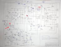
Update. I disconnected both BIAS boards and +/-Va for MOSFET.
There is about +2V on Q7 emitter, it changes a little with temperature or something, and I think it should be stable 0V, like in the working channel.
I replaced OP AMP, Q7, Q12. No result. Both feedback capacitors C43 and C49 are checked and are ok. Other capacitors do not affect my problem, according to the schematic.
I tried to freeze the transistors - no result. I think there is a leak or something, but I do not see it.
Here is the schematic with voltages measured with BIAS boards disconnected, and with disconnceted +/-Va.
Some open parts and connections on the schematic are erased in Photoshop for ease of reading.
Red voltages are for the Right channel, green for the Left (good) one.
Attachments
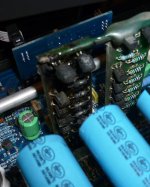
Did you check to see if the opto isolator on the bias boards are getting their voltages? In an earlier post in the version of the amp I had here, the voltage first passes via a red led on the main board. The led was blown and no voltage was arriving at the opto isolators on the bias boards. On the amp I covered there is a separate control board that first switches power to the bias boards perhaps after a warm up delay for the tubes.
I can't remember now. If your amp has this small control board or circuit first check it is switching the voltage on that goes to the white opto isolators on the bias boards. If you have the red led also check that. If you have it it should be lit if operational.
I can't remember now. If your amp has this small control board or circuit first check it is switching the voltage on that goes to the white opto isolators on the bias boards. If you have the red led also check that. If you have it it should be lit if operational.
- Home
- Amplifiers
- Solid State
- Schematic diagram of Unison Research Unico