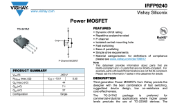
Thank you so much as_audio but I realized the audio output transistors on the device are different from the schematic that you sent me. Acoording to schematic they are IRFP240 but there are three set of 12P20 and 19N20C on mine(all of them are short circuit). By the way Left Ch Ok only right ch is burned. I don't want to disassemble the parts of the solid left channel, but if I have no reach original service manual, I will have to disassemble and measure one by one it.
Hi all, I need Unico SECONDO Service manual, if you have please, please share with me.
kind regards,
michael
kind regards,
michael

I obtained the schematic for the Unico from as_audio. Regrettably, I am still unable to repair it, possibly due to my lack of expertise. When I am able to finish, I will let all of you know how I repaired the Unico.
Hi. There is one thing you must do that is very important. Before you proceed you must dig out all of the carbon left by the burnout. Carbon is conductive so it will continue to cause problems. Take care not to damage tracks on the underside. some multi layered boards can be almost impossible to save. Once you are happy it is all gone, at least far enough away from any tracks etc you can refill the damage with epoxy and finish it with a uv solder mask.Hi all, I need Unico DM Service manual if you have please share with me. I need for some burned resistors on amplifier board.
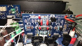
Hi I am trying to repair a Unico Hybrid for someone i recently purchased some Quad II's from. There is output but extremely low and a little distorted. A schematic posted earlier in this thread is very similar I think it was the first one posted (Rev.C?). I believe this model is the A101/2D or at least that is what it says on the main board. On the front panel it just says Stereo Valve Mosfet Amplifier. In the other schematic i saw it shows the valves as Ecc82 but this one has 2x 5814A valves. I wonder if that is correct.
I've tested most voltages and i think everything is ok. Bias between left and right ch (between both center pin of bias resistors) is around 18mv and the output transistors are very cold. I'm not really sure how the valves integrate with the amp. I'm still trying to understand the schematic.
Once i can work out the signal path i will probe with a scope. Voltages seem present and normal from what i can tell. i think the bias boards are working. They don;t have much voltage present on the actual boards max 1.7V, some action from the opto isolaters but bias seems ok so i guess they are fine.
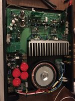
Got + and - 15V on the opp amps no pre drive transistors seem to be blown but i still need to check a few things. This is the amp with motorised volume. A heavy solid aluminum silvery white font panel. It has an Atmega8 board with 5V and 12V for the remote controll.
Just 2x outputs with biwire terminals.
Has another small board with 2x ic HCF4093 i didn't work out what for yet, perhaps motor driver or some sort of pre amp. It has phono aux but not sure how to change to phono. There are some jumpers near he bias boards but not sure what their purpose is.
Wondering if someone put the wrong vales in or if the valves are bad. It also had some water damage but very light and i've checked it over and cleaned it. Does not seem that it was powered up at the time.
Where is everyone getting their Unico schematics from?
Anyone had similar issues before i probe further?
Thanks
I've tested most voltages and i think everything is ok. Bias between left and right ch (between both center pin of bias resistors) is around 18mv and the output transistors are very cold. I'm not really sure how the valves integrate with the amp. I'm still trying to understand the schematic.
Once i can work out the signal path i will probe with a scope. Voltages seem present and normal from what i can tell. i think the bias boards are working. They don;t have much voltage present on the actual boards max 1.7V, some action from the opto isolaters but bias seems ok so i guess they are fine.
Got + and - 15V on the opp amps no pre drive transistors seem to be blown but i still need to check a few things. This is the amp with motorised volume. A heavy solid aluminum silvery white font panel. It has an Atmega8 board with 5V and 12V for the remote controll.
Just 2x outputs with biwire terminals.
Has another small board with 2x ic HCF4093 i didn't work out what for yet, perhaps motor driver or some sort of pre amp. It has phono aux but not sure how to change to phono. There are some jumpers near he bias boards but not sure what their purpose is.
Wondering if someone put the wrong vales in or if the valves are bad. It also had some water damage but very light and i've checked it over and cleaned it. Does not seem that it was powered up at the time.
Where is everyone getting their Unico schematics from?
Anyone had similar issues before i probe further?
Thanks
Is it true that you describe an Unison amp ?
Let us see some pictures if you are not sure about the model.
Let us see some pictures if you are not sure about the model.
Thanks for that. I'll be going through it again later tonight. I think the other schematic Unico Rev.C had more info but hopefully this will help.
Hope the recovery is going ok.
Hope the recovery is going ok.
I'm getting +46V and -46V at the Fets The Rev C schematic only shows +-40V and the Unico P shows +-34
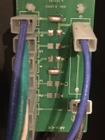
I've noticed the board that feeds the transformer from the mains has soldered jumpers. It looks like someone has changed the transformer input jumpers in the past. I'm wondering if the voltage is running too high due to the way it's set but i can't find any info on how to set it for 230V to see if it's correct. Either this or there is nothing pulling to voltage down to steady it. All the other voltages seem normal but i still need to check what voltage the bias boards should be running at. I've tested the final FETS in circuit and i think they are fine but having zero bias seems strange. Yesterday i was seeing 18mv but that was between left and right so that was dc offset not bias. Bias is zero which doesn't seem correct.
I might remove a final to test it out of circuit but i would love to know more about setting transformer input windings.
Just checked the datasheet for the Mosfets and it says max voltage is 44v so we seem to be over!
I've just written to Unison Research to ask about the primary transformer config. Lets see if they get back to me.
Attachments
Last edited:
- Home
- Amplifiers
- Solid State
- Schematic diagram of Unison Research Unico