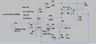
With the help of @Baudouin0 I have added gNFB to the RH807 amp as shown below. I left the original 100K Schade plate to plate feedback in while adding the 2.2K gnfb resistor. My question is there any rule of thumb on the balance between Schade and gNFB that should be used? Or is done by ear and measurements alone?
Attachments
Last edited:
The 10K resister on the 6L6 Screen needs to be 100R.
Remove R11 from the circuit until the rest is working properly.
NFB thru R11 will cause the 6L6 to be more affected by power supply ripple.
Best to leave R11 out of the circuit, it is a useless complication.
Remove R11 from the circuit until the rest is working properly.
NFB thru R11 will cause the 6L6 to be more affected by power supply ripple.
Best to leave R11 out of the circuit, it is a useless complication.
Thank you for your suggestions. On the 10K screen resistor. The parent schematic used a 340V B+ but my PS sagged a bit to the 305v shown in the model. I plan to upgrade the PT to get back to a ~340V B+, in that case the 10K screen resistor is needed to drop the screen voltage below the 807/1625 limit of 300V.
If a voltage dropping resister is used in series with the screen a capacitor of about 40 microF needs to be connected from the screen to the common (-ve) lead.🙂
Hi jhstewart9,
may I ask you why you consider useless that anode-to-grid local-feedback resistor?
I've less than 1/1000th of your know-how and experience, but I've found it to be a good method to reduce internal resistance of the power tubes, so improving the damping factor and improving the results of a mediocre output transformer too. And of course to linearize the power tubes.
Thanks!
Best to leave R11 out of the circuit, it is a useless complication.
Best to take R10 and C4 out of the circuit, it is a useless complication. Definitely leave R11 in the circuit, especially if you're unable to determine how stable the circuit will be with your particular OT.
Originally just had R11. Did a listen. It sounded nice.
Then added R10 and C4, hit it with square waves and look at signal on the scope and it was well behaved. Did a listen. Subjectively the sound improved.
I will now probably just play with trying different caps and see what that does and leave the feedback arrangement like it is. I was just wondering if there are consensus on Schade PP versus gNfb or in combination etc. Seems like the answer is "no" (so far).
I prefer 100% Schade if at all possible.
Yes, putting the feedback around the OT will make for better objective measurements, since you are ironing out the negative contributions of the output transformer. It does come with its own set of negative consequences that I aim to avoid.
Yes, putting the feedback around the OT will make for better objective measurements, since you are ironing out the negative contributions of the output transformer. It does come with its own set of negative consequences that I aim to avoid.
If a voltage dropping resister is used in series with the screen a capacitor of about 40 microF needs to be connected from the screen to the common (-ve) lead.🙂
Why? I have read some posts that suggest letting the screen follow the anode gives a quasi-UL operation to the tube. Any merit to this?
You are feeding it from the supply rail, not the anode here. The voltage drop across the screen resistor will change at varying signal current if you don't have a capacitor there to stabilize the voltage. This will also have the benefit of some ripple filtration and better noise rejection overall. Quieter screen supply equals quieter output.
That was my question on the quasi UL. As the anode voltage drops screen current will increase causing the screen voltage to follow the anode voltage. Which is similar to what a UL tap would do. Or do I have this backwards?
So the unbypassed screen resistor puts the operation neither in Pentode mode or UL mode, but someplace in between?
So the unbypassed screen resistor puts the operation neither in Pentode mode or UL mode, but someplace in between?
Why? I have read some posts that suggest letting the screen follow the anode gives a quasi-UL operation to the tube. Any merit to this?
Best idea is to stop reading bad advice & try running the screen of a power tube thru an unbypassed 10K screen resister. Then come back & tell us how the power available was insufficient.🙂
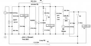
12AT7 6L6 FB Pair First Pass
I've taken the OPT to be 6.5K to 8R, let me know the real number. 6.5 K is too high.
Measure the DC resistances of the OPT primary & secondary if possible & advise.
I'll do a 2nd pass with the corrected OPT numbers. And get some performance numbers.
On the keypad, Key A sets Triode or Pentode operation of the 6L6
Key X sets Schade FB On or Off
Key Z sets Loop FB On or Off
Key S sets the 8R load On or Off
A 2nd AC Generator allows injection of PS noise onto the B+.
Assumed values are used for the OPT Primary, Secondary & Iron Core Losses.
As is the stage gains are 30.83 for the 12AT7, 25.03 for the 6L6 & 0.0318 for the OPT
Attachments
The transformer primary is 6.5K (edcor). The 807SE designed called for a 6K. It is what it is now. The output tube is a 1625(807), I used the 6L6 for the spice model.
I think an issue I need to correct first is my B+ is 40V lower than design, so my operating points are most likely off. Tonight I changed the 10K screen resistor to a 2K to pull the screen voltage up a bit and gave a listen. Tomorrow I'll add a 33uf bypass (its what I have in my parts bin). On the bench I am getting about a smidge less than 5W before clipping. At 1W the distortion figures are really good, 2nd H is about 30db down if I can believe my FFT. Freq response starts to roll off at around 12Khz which is fine with me. My ears are rolling off before that.
I really appreciate all the advice and teaching.
Unlike triodes, pentodes are very much affected by the load impedance. Too high is not a good place to be. For example, a common loudspeaker spec'd at 8R will be about 6.5R in the midband. But depending on speaker loading the LF will have a couple of peaks that could be 2-3X that. A similar rise occurs at the HF end.
I usually design for a target of somewhat lower load impedance than the recommendation in the tube manual. That number is for an ideal resistive load. Not many loudspeakers look like that.
The tube models I used are ideal, very much like you would see in a EE text book. In this case the models are voltage controlled current sources, mA/Volt. In parallel with their plate resistance, all taken from the published specs. No DC voltages required, simplifies the analysis.🙂
If you have a DMM, get the OPT resistance of the primary & secondary winding's, they can be stuffed into the simulation & proceed from there.🙂
What kind of FFT are you using, what is the resolution, how many bits?
Each bit of resolution gets 6 db. So 12 bits would theoretically get 72 db & so on.
I will try and get those OPT measurements tomorrow, I am listening to the amp now.
The FFT is built into my scope, it up to 1millions point but I don't remember how I had it setup when I was playing with it. I was looking over the specs and couldn't find the ADC resolution yet.
The FFT is built into my scope, it up to 1millions point but I don't remember how I had it setup when I was playing with it. I was looking over the specs and couldn't find the ADC resolution yet.
What is the make & model of the scope? I sold 100s of scopes while at HP. And used many what was state of the art while in my research job, long ago. I've four different Pico Tech scopes here, I gave away my 2-channel, 100 MHz scope about 10 yrs ago.
And sold many Spec As & Network Analyzers while at HP, R&S. And later from Aeroflex. But got a lot of my education on the factory floor. And later on the job in the field. Traveled a lot.🙂
And sold many Spec As & Network Analyzers while at HP, R&S. And later from Aeroflex. But got a lot of my education on the factory floor. And later on the job in the field. Traveled a lot.🙂
From the published Spec that is a very good scope. It will be of great help as you try more electronics in the future.
Let me know the OPT winding resistances, otherwise I'll go ahead with the numbers I've assumed.🙂
Let me know the OPT winding resistances, otherwise I'll go ahead with the numbers I've assumed.🙂
- Home
- Amplifiers
- Tubes / Valves
- Schade P2P and gNFB in RH807