Here’s a nifty reference to how the zener follower supply operates. Pa recommends 2 mA through the zeners. A little more wouldn’t hurt of course 
https://www.firstwatt.com/wp-content/uploads/2023/12/art_zv3.pdf
https://www.firstwatt.com/wp-content/uploads/2023/12/art_zv3.pdf

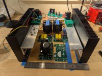
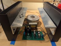
Did some test-fits to size the SCG + TDV follower chassis. I bought one of the Hammond steel enclosures like I've used for tube amps in the past. Going to mount the 4U heatsinks to the side like wings, put the power transformers and SCG regulated supply board underneath, and mount the rest up top. It will be a real franken-chassis situation, but it's a cheap way of doing it. Lots of drilling ahead of me.
Attachments
Last edited:
I am happy to report that pushing 5 mA through the Zener string has eliminated any hint of noise.
To put a cherry on that cake, line voltage today is a little higher than yesterday's, and I get ~70V out of the regulator.
I configured the preamp board at 35V.
I reran some measurements to validate the new setup and:
THD+N: 0.18%
THD: 0.12%
H2: 0.12%
H3: not measurable accurately
-2.2 dBr / -1.31 dB @ 20 Hz
Listening test says "a little dryer than yesterday", but that's normal since the H2 is nearly halved compared to yesterday.
It really polishes the edges of that class-D amp.
So, end of that side saga: Make sure your Zener string is well fed, or there'll be noise at the gate of the MOSFET and it will get amplified.
I am happy with my 5 mA. I am sure 2 mA would be enough since the 58V regulated supply had no noise at that level.
Just don't let it starve! 🙂
I am going to sound like I am advertising, but The Art of Electronics is quite clear that anything below 1 mA will lead to significant noise. I should read that book more often.
I'll try adjusting the current through the Zener string to see if I can have the same result and achieve a higher output voltage from the regulator circuit. Thanks for investigating this!I am happy to report that pushing 5 mA through the Zener string has eliminated any hint of noise.
Sounds like a good book.... glad it helped.
You helped me more than the book, as it was your message that made me check the book.
The book is great, but it’s very dry and I go to it only to verify suspicions.
Thanks again!
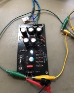
Also that portable soldering tool is a little marvel. It’s powered by an external 100W SMPS and works very well:

Hooray! Nice work, @ElArte! And thanks to William as well! Glad you found the source of the noise. I’ll make this change to the power supply schematic.
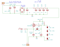
PS together and a quick reality check before moving on... output voltage is spot on 70 volts with a string of twelve 6.2V zeners. Q1 is an IRF510. An eagle eye may notice something different about "R6" there. I also hacked in a TVS diode (device is a 5KP110A, a little hard to see in the picture) to give it some surge protection. This won't use much power, and I will probably just leave the gainstage on all the time.
Attachments
Last edited:
Awesome! 6.2V zeners have close to zero tempco so there is less drift. Not a big deal here because a little drift doesn’t make a big difference, but if less drift is desired for a DAC supply, for example, then 6.2V zeners are the way to go. Sweet and clean build!
Ya this is stuff inspired by Rod Elliot's AN-008 page. I had a bunch of the 1N4735's, and putting them together wasn't too big a deal. The JFET current source was just one extra part to the circuit to really lock in that reference. I'm using a J112 with a 220 ohm resistor there.
I have read that 6V is where zeners are the least noisy and noise increases as the voltage increases. Also higher current is less noisy. I usually aim for 20 percent dissipation of the zener.
PS together and a quick reality check before moving on... output voltage is spot on 70 volts with a string of twelve 6.2V zeners. Q1 is an IRF510. An eagle eye may notice something different about "R6" there. I also hacked in a TVS diode (device is a 5KP110A, a little hard to see in the picture) to give it some surge protection. This won't use much power, and I will probably just leave the gainstage on all the time.
Clever, clever.
It took me a second to see the 4X3 Zs.
I think what I learned here is that input VAC, sag, R6, Zener string and MOSFET determine output voltage together, if you really really want to be precise.
As Rahul mentions, super precision isn't necessary here, fortunately. Most important is just making sure the basics are right.. close enough V-out to the goal, adequate V-in to V-out headroom, and "enough" reference current (as we found out). Improved ripple rejection, almost no drift, and possibly less noise as Ben mentions are just icing on the cake..
@william2001 thanks for that reference to the Rod Elliot pages. I checked it out and he has a nice explanation of zeners as always. If we look at the chart and where the zener knee is and the knee mA for 18-20V in the table that follows on his page, most of the knees are < 0.5 mA. In fact, all above 10V are 0.25 mA. Above the knee, the zener starts to regulate. Of course, we learned that zeners like a bit more current, so that's great to know. Don't get close to the knee! Practical knowledge on zeners
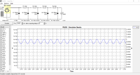
One thing to mention, the 5-section RC filter is extremely effective. I got it off of Morgan Jones's Valve Amplifiers. It looks simple but it reduces ripple by a factor of 23,333 times, or -87 db, almost the full scale resolution of a CD (16 bits). See attached PSUD simulation. And this is before the regulator FET, which provides additional 25-40 db of suppression. Between the ripple filter and the regulator, we should have a clean, stable supply. There is also C4 on the PCB to control zener noise.
One thing to mention, the 5-section RC filter is extremely effective. I got it off of Morgan Jones's Valve Amplifiers. It looks simple but it reduces ripple by a factor of 23,333 times, or -87 db, almost the full scale resolution of a CD (16 bits). See attached PSUD simulation. And this is before the regulator FET, which provides additional 25-40 db of suppression. Between the ripple filter and the regulator, we should have a clean, stable supply. There is also C4 on the PCB to control zener noise.
Attachments
Yeah, that’s a good summary. Also, the R’s in the RC filter drop a bit of voltage, and higher the draw higher the drop. That ought to be included in the calcs for sizing R6.I think what I learned here is that input VAC, sag, R6, Zener string and MOSFET determine output voltage together, if you really really want to be precise.
Unfortunately, a decoupling capacitor across the zeners (C4 here) doesn't really improve the zener shot noise. The cap value would have to be huge to have any effect. The dynamic resistance is just far too low. A larger value there (say 220uF or something) can give the supply a nice gentle start up, if that behavior was desired for some application. This is all nit-picking of course, the supply still works great..
Last edited:
- Home
- Amplifiers
- Pass Labs
- Schade Common Gate (SCG) Preamp