For anyone searching for a toroid power transformer to use with this project, I found this 50VA unit at Mouser:
https://www.mouser.com/ProductDetail/Triad-Magnetics/VPT230-220?qs=wkKrz7WmEgMVJQHjyRuIng==
Ignore the Mouser listed specs, go straight to the Triad Datasheet with diagrams: 2X 115VAC primary to 2X 115VAC secondary@.220A each
Should be a perfect electrical fit for this preamp.
https://www.mouser.com/ProductDetail/Triad-Magnetics/VPT230-220?qs=wkKrz7WmEgMVJQHjyRuIng==
Ignore the Mouser listed specs, go straight to the Triad Datasheet with diagrams: 2X 115VAC primary to 2X 115VAC secondary@.220A each
Should be a perfect electrical fit for this preamp.

That is an interesting observation and hypothesis. I seem to recall from earlier measurements that the SCG distortion didn’t increase at the same rate with level as that tube preamps. But I will check and report back. Also, the rounding effect is at all volumes and material, not just at loud levels or complex stuff. The first time I plugged the 300B into the circuit and heard it, I brust out laughing—it was sooo good. It feels like the signal has just passed through some kind of tunnel and has been cleansed and sweetened. So strong is the effect. It is really great sound.I have been pondering the relationship of harmonic distortion and enjoyment of reproduced music with respect to your 300B and SCG preamps. Like you I have SIT/VFET single ended follower amplifiers and enjoy a bit a second harmonic distortion. Even though my horn speakers are very sensitive (102dB), my SE amplifiers vary from 5W to 50W output. With my sensitive speakers I can take advantage of the first Watt as most of the time, and perhaps all of the time, I am listening to the first Watt and the lower distortion level that comes with the first Watt.
So that got me thinking about your 300B preamp, and whether its distortion at higher output voltage is higher than that of your SCG preamp. It would be interesting to compare the distortion levels at higher output voltages. Of course the sensitivity of your speakers and the actual output voltages at your listening levels would be factors.
I received notification from Mouser that the STP30N10F7 part has been deemed EOL and won’t be restocked. Still a few available at a reasonable price. Grab a couple pairs if you plan to build this preamp. I also bought a few and should have enough for this group. I’m sure there are other great FETs out there but I know this one sounds good. Plus who knows when the STQ parts will be restocked again.
Vunce has already finished wiring up the preamp PCB--man, that's fast! Here's a quick write-up of the power up procedure:
Safety first: This is not your typical solid state circuit with low voltages. This circuit has potentially lethal voltages! There is between 150V to 200V DC on the board. Please use caution. If you are not sure what that means, seek help. Read through the tube safety pages on this forum. If you are still not comfortable, seek out someone who can test the circuit for you.
Get one channel working first following all the steps below before moving to the second channel. Before applying power make sure R107 and R207 are disconnected and then follow the steps below.
A. Test that the regulator is working. Remember that the FQP part has the gate and drain pins reversed on this first set of four boards that went out.
B. Set the CCS current.
D. Set gain FET operating point. Connect voltmeter across TP1, Vd, and TP0, GND. Turn RV102/2020 until you measure 65V. And you're done. Now repeat for the other channel.
Safety first: This is not your typical solid state circuit with low voltages. This circuit has potentially lethal voltages! There is between 150V to 200V DC on the board. Please use caution. If you are not sure what that means, seek help. Read through the tube safety pages on this forum. If you are still not comfortable, seek out someone who can test the circuit for you.
Get one channel working first following all the steps below before moving to the second channel. Before applying power make sure R107 and R207 are disconnected and then follow the steps below.
A. Test that the regulator is working. Remember that the FQP part has the gate and drain pins reversed on this first set of four boards that went out.
- Don't wire in R107 and R207 (all other parts can be wired at this time). R107/207 is the resistor just before the CCS. This will keep the rest of the circuit from seeing any voltage.
- Leave all jumpers in the zener stack open.
- With the above config, connect voltmeter between TP4 and TP0 or ground. Power it up. If all goes well, you should read the sum of the zener stack at TP4. If you followed the parts list, it should be around 130V.
- Switch it off, let the caps drain--they will drain very slowly because there is no load yet. Be careful because it can have more than 160V on the circuit and it drains slowly. Best way is to walk away for 5 minutes.
- After voltage has dropped to a safe level (<5V), wire in R107 and R207.
B. Set the CCS current.
- Use alligator clips and leads to shunt Rlim1/Rlim2 to ground. The leg closer to the FETs (connected to R103/203) is the one to shunt to ground. Another option is to create a shunt to ground from the output capacitor (C103/203) leg that is connected to Rlim. That's the leg closer to the FETs.
- Connect voltmeter between TP4 and TP5, i.e., across R107/207. Now, turn the RV101/201 pot. For TO-220 parts, set it to 23 mA. For 23 mA, it should read 23 mV. For TO-92, i.e., the STQ part, I would set it to 14 mA. For JFETs, it would be lower. What you are shooting for is 3-4 mA more than what you expect through the gain FET. This is because the Schade network of Rsch and Rg drains about 3-4 mA (for the 10k/1k combo) of current and this should be accounted for in the current through the CCS.
- If all goes well, and you can successfully set the current, switch of power and take out the alligator clips.
D. Set gain FET operating point. Connect voltmeter across TP1, Vd, and TP0, GND. Turn RV102/2020 until you measure 65V. And you're done. Now repeat for the other channel.
Rather than spending money for MosFets, I'd rather use what's in my parts box, so I'm looking for recommendations. I have old school IRF840, 830, 711, 530, IRFP9610, 9540, 9140, LND150, ZVN0545. I have several fets for possible use as the input stage (or not), K170, K369, J174, 2N5462, U310 and J201. I have IXCP10M and DN2540 for the CCS. I know that's a bit of a list, but general guidance would great...I'm more of a tube guy.
Pretty much any FET with pentode-like curves can be made into a triode, but, just like tubes, not every device will make for a good choice here. Each FET has characteristics like capacitance and internal resistance that will define its sound.
You have good candidates there. I’ll look up the spec sheets for some of those later. The IXCP and DN parts will work fine as a CCS. I use the same dual DN2535 as the CCS load in the 10Y preamp.
The objective of this effort was to see if alternatives to unobtanium triodes, SITs, and VFETs can be made to work and sound good. Most ordinary FETs ahould work here as long as you find the sweet spot. The circuit lets you dial in the current and voltage for the gain FET and thus provides total flexibility in trying to find the sweet spot. Some devices are definitely better sounding than others.
Last edited:
Good News!
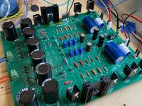
SCG preamp is singing away on the work bench 🙂.
Initial build is setup with STP30N10F7 as gain FET and FQP12P20 as lower FET.
Vital Stats:
Regulated- 126V
CCS- 23mA
TP1- 63V
TP2- 22V
TP3- 16V5
Q103/203- Get very hot so I installed TO-220 extruded 37mm tall heatsinks.
The other FET’s use clip on heatsinks.
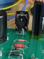
Additional build notes, Q11/21 drain/gate legs are crossed with heatshrink tubing to prevent shorting. All diodes and higher wattage resistors are lifted a few mm’s off the pcb.
TP0 is connected to earth gnd via a 10R NTC.
Music sounds very good on the bench and the background is silent between tracks. Next step will be to setup SCG in the main system for better impressions.
Wonderful work here Rahul! Thanks for sharing the SCG preamp with us. More tweaking fun to come…..

SCG preamp is singing away on the work bench 🙂.
Initial build is setup with STP30N10F7 as gain FET and FQP12P20 as lower FET.
Vital Stats:
Regulated- 126V
CCS- 23mA
TP1- 63V
TP2- 22V
TP3- 16V5
Q103/203- Get very hot so I installed TO-220 extruded 37mm tall heatsinks.
The other FET’s use clip on heatsinks.
Additional build notes, Q11/21 drain/gate legs are crossed with heatshrink tubing to prevent shorting. All diodes and higher wattage resistors are lifted a few mm’s off the pcb.
TP0 is connected to earth gnd via a 10R NTC.
Music sounds very good on the bench and the background is silent between tracks. Next step will be to setup SCG in the main system for better impressions.
Wonderful work here Rahul! Thanks for sharing the SCG preamp with us. More tweaking fun to come…..
Attachments

Last edited:
Just awesome, Vunce! Thanks for sharing! Really love the attention to detail and how you did the twisted leg with the shrink wrap. Let us know how it sounds.
nice...... can't wait for my board to arrive...Good News!
SCG preamp is singing away on the work bench 🙂.
Initial build is setup with STP30N10F7 as gain FET and FQP12P20 as lower FET.
Vital Stats:
Regulated- 126V
CCS- 23mA
TP1- 63V
TP2- 22V
TP3- 16V5
Q103/203- Get very hot so I installed TO-220 extruded 37mm tall heatsinks.
The other FET’s use clip on heatsinks.
Additional build notes, Q11/21 drain/gate legs are crossed with heatshrink tubing to prevent shorting. All diodes and higher wattage resistors are lifted a few mm’s off the pcb.
TP0 is connected to earth gnd via a 10R NTC.
Music sounds very good on the bench and the background is silent between tracks. Next step will be to setup SCG in the main system for better impressions.
Wonderful work here Rahul! Thanks for sharing the SCG preamp with us. More tweaking fun to come…..
Yes, no problem here.(Q11/21)
Q103/203 is the hottest followed by the gain FET. The clip-on heatsink is boarderline on this FET. If a TO-220 choice becomes permanent, I’d remove the socket and solder it to the pcb with a larger heatsink.
Ra,
Did you play around with extending the SSR delay time to 5-10 seconds?
Q103/203 is the hottest followed by the gain FET. The clip-on heatsink is boarderline on this FET. If a TO-220 choice becomes permanent, I’d remove the socket and solder it to the pcb with a larger heatsink.
Ra,
Did you play around with extending the SSR delay time to 5-10 seconds?
Last edited:
You have left out C102 and 202, any reasons? I recalled Ra7 mention that these play a part in some improvements in the sound.Yes, no problem here.(Q11/21)
Q103/203 is the hottest followed by the gain FET. The clip-on heatsink is boarderline on this FET. If a TO-220 choice becomes permanent, I’d remove the socket and solder it to the pcb with a larger heatsink.
Ra,
Did you play around with extending the SSR delay time to 5-10 seconds?
No reason, to get started the bypass caps are not necessary. Silmic II caps are installed at C102/202, I will tweak with the bypass caps later 😉.
Also, be very careful desoldering on this board. A couple of pads lifted when removing Q103. If anyone is planning to experiment with FETs, sockets are highly recommended.
Also, be very careful desoldering on this board. A couple of pads lifted when removing Q103. If anyone is planning to experiment with FETs, sockets are highly recommended.
wow thanks for the warningNo reason, to get started the bypass caps are not necessary. Silmic II caps are installed at C102/202, I will tweak with the bypass caps later 😉.
Also, be very careful desoldering on this board. A couple of pads lifted when removing Q103. If anyone is planning to experiment with FETs, sockets are highly recommended.
I butchered the board during testing, especially the reg FET and haven’t had pads lift. But good to know. Next board will have larger pads for sure, but I’ll look up other ways to prevent that.
No, I haven’t played with delay time. In my build with the Salas shunt reg, the thump was instantly after flipping the switch and so a one second delay was enough, but with this reg, it comes on quite slowly.Yes, no problem here.(Q11/21)
Q103/203 is the hottest followed by the gain FET. The clip-on heatsink is boarderline on this FET. If a TO-220 choice becomes permanent, I’d remove the socket and solder it to the pcb with a larger heatsink.
Ra,
Did you play around with extending the SSR delay time to 5-10 seconds?
- Home
- Amplifiers
- Pass Labs
- Schade Common Gate (SCG) Preamp