I'm a first-time speaker builder, and a few years ago I purchased a pair of D2905/9900 Revelators and a pair of 18W/8545 woofers. I have long-since lost the crossover design I had intended to use. The Reference Monitor
http://www.audiocomponents.nl/speakers/scanspeak/reference/scanspeak-reference_eng.htm
seems to be an ideal speaker design, but it uses a 18W/8546 woofer instead of the 8545.
I'd be interested if anyone could inform me as to what changes to the crossover I would need to implement in order to use the 8545 for this speaker design? The only other speaker I've been able to find on the net using these drivers is at:
http://www.audiocostruzioni.com/a_d...n-revelator.htm
Any other suggestions would be appreciated as well.
Thanx
There are several projects here:
http://www.troelsgravesen.dk/ScanSpeak.htm
Hope you find something helpful.
Specifically this?
http://www.troelsgravesen.dk/SP95.htm
http://www.troelsgravesen.dk/ScanSpeak.htm
Hope you find something helpful.
Specifically this?
http://www.troelsgravesen.dk/SP95.htm
Different driver - but more specifically this one
http://www.troelsgravesen.dk/Amish_8545_9500.htm
But then a different tweeter but might only need different attenuation
http://www.troelsgravesen.dk/Amish_8545_9500.htm
But then a different tweeter
but might only need different attenuation
a Cross-over
Vance Dickason published a design for a Studio Monitor - LDC6 - in the 6th Edition of his "Loudspeaker Design Cookbook"which is for the two drivers that you have.
He gives several plots he measured of the drivers' responses and final system responses on/off axis, etc ...
It is very well worth reading.
I do not have the facilities to copy the article and post it here, and doing such may contravene his Copyright or that of the Publisher - Audio Amateur Corporation.
There has recently been a new 7th Edition of this book published, and several of the Mail-order sellers list stock.
From the description of added contents on Audio Amateur's own mail-order web-site :- www.audioXpress.com , the added chapter in the 7th Edition about loudspeaker cabinet diffraction, and apparently numerous plots are given of its effects likely including several of Dickason's methods of reducing such, would seem to make this book well worth owning.
I am presuming the LDC6 is still included in the 7th Ed. , but do email and ask "audioXpress" to confirm.
I will list the cross-over components and connections here for you now :-
For the woofer arm there is a series CR network of 10 uF + 1 ohm/10 watt connected in parallel with the 8545 for impedance correction, then a 3 mH inductor connected between the 8545's positive terminal and the amplifier positive connection.
Together with the 8545's own roll-off this network causes a 4th order filter slope.
In his calculations for the component values Dickason says he has included allowance for the Time Delay of the path length difference of the woofer being further from the listener than the tweeter is.
For the tweeter arm there is a 20 uF cap. connected to the 9900's positive terminal, then a 0.2 mH inductor connected from other end of the cap. to the 9900's negative terminal, and an 8 ohm/10 watt resistor connected to that CL junction. The other end of the 8 ohm is connected to an 8 uF cap. and the other end of this cap. is connected to the amp's positive connection.
Together with the 9900's own low end roll-off this network forms a 4th order filter slope.
The tweeter filter is basically a T shape.
The cross-over point is 2 kHz.
This is an often used type of cross-over and no more complicated than necessary. I am confident from all the measurements that Dickason has published as plots that this cross-over does work as he describes.
I have not constructed this Monitor myself, because I am more interested to use the Scan-Speak 18W8531 and D2905/9700 drivers, -{but I haven't bought those yet, nor worked out any crossover component values as I will need to make measurements on the drivers}.
I think this cross-over is worth considering as well as the other cross-over designs that Forum members have posted Links to, as each will have different audible effect - some-what subtle differences between some and more obvious difference between others.
best wishes,
Here is a link to the Vance Dickason project.
The woofer is the 18W8545K00, though.
http://www.partsexpress.com/resources/diy/vance/ldc6kit.html
Mingo
The woofer is the 18W8545K00, though.
http://www.partsexpress.com/resources/diy/vance/ldc6kit.html
Mingo
Hi Raygun,
I've build the studio monitor from Vance that uses the same drivers as you want to use.
But I was not so very happy with the result. The midrange was not so spectacular for the price. Also the hights where to much into the front. When you listen a long time it was very fatigue. (the speaker has large bumps in the midrange)
You can read everything in my tread:"Closed box design:Scan Speak monitor"
But I've good news for you. I've worked more then half a year to improve the crossover. The result is very spectacular.
With the crossover from Vance the frequency responne has large bumps +/- 2.5dB in the midrange. Alse the phase is very poor.
I've my new design of the crossover ready on paper and it looks very spectacular. The frequency respons is +/-1 dB exept one small peak from baffle (reflection agains speaker frontpanel) and the peak above 10Khz but this is normal for the tweeter.
Also the phase of my new crossover is very spectacular. I've a deep null with reversed polarity more then 40dB. With the original studio monitor from Vance I measured less then 20dB
I'm going to post everything on my thread:Closed box design:Scan Speak monitor""in the comming days.
So you can look to my mesurements and my new filter design.
I hope I can build it soon.😉 😉
Jonasa,
flat response from any given x-over does not always sound good....this is not meant to be a critcism of your x-over...just an observation.
With respect to your x-over, you need to listen to it first and like the sound before recommending it.
flat response from any given x-over does not always sound good....this is not meant to be a critcism of your x-over...just an observation.
With respect to your x-over, you need to listen to it first and like the sound before recommending it.
ttan98
Yes you are right, but I was a little bit to exited about my crossover because it looks so good on paper.
Ofcourse we will know it for sure if I've build it.😉
Yes you are right, but I was a little bit to exited about my crossover because it looks so good on paper.
Ofcourse we will know it for sure if I've build it.😉
one way without spending a lot of money on x-over is to use active x-over.
quality passive x-over are very expensive.
I am designing 6 channel amps with digital x-over. With digital x-over you can just DIAL up the type of values one needs, butterworth, linkwitz, 1,2,3 order, etc.
quality passive x-over are very expensive.
I am designing 6 channel amps with digital x-over. With digital x-over you can just DIAL up the type of values one needs, butterworth, linkwitz, 1,2,3 order, etc.
At this point I'm leaning towards the Matthias Brennwald crossover / design. It uses the exact same drivers as I have (most of the others referenced use a slightly different woofer -- e.g. 8545K, etc.)
Has anyone else built, or more importantly, heard this design?
Has anyone else built, or more importantly, heard this design?
RAYGUN
I have heard a loudspeaker system with the 8545K00 crossed over at 2.8kHz -{which seems to be the cross-over frequency of Matt Brennwald's also}- to a Visaton KE 25 SC tweeter -{has flatter response than Scan 9900 above 10kHz.
I have not seen the x-over, nor schematic for -{it is the Designer's secret}- but from description of by him, and his measured plots, and my listening, it seems to be very similar to the types both Brennwald and Dickason have used with regard to roll-off summing to 4th Order as combination of electrical network and driver mechanical roll-offs.
Sound is very clear and reveals details from recordings well and has plenty of up-front reality as well as depth when such is in the recording.
Brenwalds x-over looks fine on paper, but for one aspect :-
he says about his L-pad on the tweeter - "it flattens the impedance peak very well too" -
well, it does on paper, but that 8.9 ohm resistor in series with a 6 ohm only tweeter will ruin the damping factor, thus one will not hear accurate Transient response -{fine if one doesn't want to and some listeners prefer such}- and this will be compounded by passing about 60% of the signal around the tweeter via that 10 ohm resistor before the Transient has even reached the tweeter.
He does not say why he has used the Reverse orientation of L-pad rather than the usual configuration which does the same flattening of the impedance peak as his, and does not reduce the Transient response too such degree.
Thus I recommend you connect R5 directly in parallel with the tweeter and connect R6 from the junction of new R5 and tweeter positive terminal and across to the junction of L3 and C4.
You will have to use different values of Resistance for R5 and R6 in their new positions to keep the same attenuation as Brennwald says the tweeter needs and to keep the network at the same Impedance so as to work with L3 and C4 at 2.8kHz.
For new R5 use 3.9 ohm - 5 watt may suffice, but 10 watt safer choice if you intend to play the speaker loudly.
If you are buying specifically designed for loudspeaker cross-over resistors, the nearset value may be 4 ohm, and that will be fine as the difference will be insignificant in this circuit.
For new R6 use 3.6 ohm - for this use two 1,8 ohm resistors in series, and 5 watts each minimum, but higher power resistors will be a safer choice as this resistor pair drops a lot of power when you are playing the speakers loudly.
Brenwald's x-over is useful because if you find the sound of Vocal recordings is not quite natural enough, or if Instruments sound a little thin and not enough substance in Timbre, you can increase the resistance of R2 a little till you get a sound you may prefer without having to change any of the other components.
Regards,
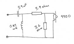
Thanks for your expertise Alan!
Just to be certain, I've attched a jpg of what I think you've suggested -- let me know if I'm in error.
What you've suggested also looks similar to the design for the Scan Speak Reference Monitor 4 crossover (first link in my original post), except the values are 4.7 ohms for R5 and 18 ohms for R6. Any reseason for the differences?
Thanks again 🙂
Attachments
Hi Robert
You have got it half correct - the resistors are drawn in the correct positions in the circuit for the L-pad,
But, the values are not.
Swap the two values around - put the 3.9 in parallel with your 9900, and put the 3.6 in the series position.
With the 4.7 ohm and 18 ohm his filter will have a slightly steeper slope at its start at the x-over frequency and will be not quite as much attenuation there, and not as much over-all shelf attenuation of tweeter output.
This is probably because he is using a different woofer to yours -{8546 instead of 8545}- thus I'm guessing 8546 may be slightly higher in sensitivity, and as he has a different lo-pass filter on it, a slight change of hi-pass filter shape may be required for the two drivers outputs to add to flat reponse at cross-over freq.
Such is quite common.
I see he has specified only 4 watt resistors.
Even though his 4.7 and 18 ohms will be dropping less power than a 3.6 and 3.9 ohms I really think the series resistor needs larger than 5watts to stay cool inside a sealed cabinet that will have absorbant material in it which will get warm and stay warm !
Resistors are not expensive, and 10 watts is safer for both in your case.
There seems less of what Dickason says is allowance for the Time Delay path in Brennwald's x-over, thus you may find you will get the flattest response a little below the tweeter vertical axis - perhaps as low as the woofer axis, though this will change a little with listening distance from the loudspeakers.
Thus if you were planning to use the speakers on low stands they may sound better balanced in tone and more coherent in overall sound if you put them up-side down - woofer at top and tweeter underneath.
regards,
Hi, i bought 18w 8531g00 and d2905 9700 but cant find any crossover on the web.
Does anybody help me? It is a 2 way 32ltrs
Regards
Does anybody help me? It is a 2 way 32ltrs
Regards
Troels did something similar:
http://www.troelsgravesen.dk/SP95.htm
Is there much difference between the ferrofluid D2905 9500 and the bare 9700?
http://www.scan-speak.dk/datasheet/pdf/d2905-950000.pdf
http://www.scan-speak.dk/datasheet/pdf/d2905-970000.pdf
I wouldn't have thought so. Particularly with that 8.2R shunt to take out the different Fs resonance which must be the result of ferrofluid in the 9500.
The Troels' point on the 9500-9700 differences: Why ScanSpeak tweeters 9500 and 9700 aren'
IMHO, if I had to change only the tweeters to build speakers, I'd build those: Zaph|Audio - ZRT - Revelator Tower
Ralf
IMHO, if I had to change only the tweeters to build speakers, I'd build those: Zaph|Audio - ZRT - Revelator Tower
Ralf
- Home
- Loudspeakers
- Multi-Way
- Scan-Speak crossover help