Yes, you can.I can't find 500 and 800 ohm resistors.
Can I use 820-510 ohms?
L=1.5uH. Diameter of the enameled conductor=1mm, diameter of the air coil=10mm, number of turns=20, lenght of coil=20mm. The diodes could be a SMD type which has the same pattern of the pads. The reverse voltage >200V, If>5A.

Всем хорошего настроения. Кто из участников форума проводил сравнения по качеству звука этого усилителя Сара 2016 года с такими, например, как Apex A40, A33, A23, SR200. Хотелось бы узнать мнение участников форума, каково их мнение, хотелось бы услышать ответ на заданный вопрос?
 This is an English language forum. You must post in English:
TRANSLATION:
Good mood to you all. Which of the forum participants compared the sound quality of this 2016 Sarah amplifier with, for example, Apex A40, A33, A23, SR200. I would like to know the opinion of the forum participants, what is their opinion, I would like to hear the answer to the question asked?
This is an English language forum. You must post in English:TRANSLATION:
Good mood to you all. Which of the forum participants compared the sound quality of this 2016 Sarah amplifier with, for example, Apex A40, A33, A23, SR200. I would like to know the opinion of the forum participants, what is their opinion, I would like to hear the answer to the question asked?
Last edited by a moderator:
Всем хорошего настроения. Кто из участников форума проводил сравнения по качеству звука этого усилителя Сара 2016 года с такими, например, как Apex A40, A33, A23, SR200. Хотелось бы узнать мнение участников форума, каково их мнение, хотелось бы услышать ответ на заданный вопрос?
TRANSLATION:
Good mood to you all. Which of the forum participants compared the sound quality of this 2016 Sarah amplifier with, for example, Apex A40, A33, A23, SR200. I would like to know the opinion of the forum participants, what is their opinion, I would like to hear the answer to the question asked?
I do not know how good is the sound of Apex A40, A33, A23 or any Apex amplifier. They probably sound really good. All I can say is that S.A.R.A.-2016 has a great sound. S.A.R.A means : SymmetricAmplifier by RaimondAudio and 2016 is the year of birth.
I am glad to hear that you like it.superb sound.
thank you raimond (greierasul) and alex-mm for the work
I missed most parts, so I ask a bit late: no need for an offset adjustment? Is it dependant under the quality of the components? Tnx.
I replaced R9 and R10 (100 ohms)with 50 ohm resistors and connected a 100 trimmer in series with themI missed most parts, so I ask a bit late: no need for an offset adjustment? Is it dependant under the quality of the components? Tnx.
In the most cases the offset is below 20mV. You don't necessarily need adjustment but if you want, you can choose any type of DC offset reduction circuit.I missed most parts, so I ask a bit late: no need for an offset adjustment? Is it dependant under the quality of the components? Tnx.
'Cause I've asked several times in other threads: I like your double Sziklai design instead of a 3EF, and I like that you proved it is working indeed!
Best regards!
Best regards!
There is no problem with Sziklai pair in a driver position. There are many benefits. In fact we have 3 transistors gains like 3EF but there are only 4 Vbe instead of 6Vbe. The Vbe multiplier will work easier. Then the power transistor of Sziklai pair will not count in a thermal economy. Only the first, small transistor will count, transistor which is in class A an has a constant temperature. Another great benefit of Sziklai pair in that position is the output impedance which is very small becasuse there is a very strong local negative feedback. That help the base of the final power transistors, especially at turn-off and turn-on. That Sziklai pairs in the driver position are the "secret sauce" of the output stage.'Cause I've asked several times in other threads: I like your double Sziklai design instead of a 3EF, and I like that you proved it is working indeed!
Best regards!
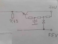
for GREIERASU . when I made my PCB instead of R61 (R46) I put an electronic filter that I can later modify in the stabilizer. I want to supply the finals and pre-finals with 55v and the input part with 60-65v. something like the next drawing. advice or help if possible. I use Google translate . anyway thanks in advance
Attachments
Most probably the first guy to prove it was Sziklai himself although it is not exactly know if he's the real inventor of that pair.'Cause I've asked several times in other threads: I like your double Sziklai design instead of a 3EF, and I like that you proved it is working indeed!
Best regards!
As Raimond said once the inspiration came from another romanian fellow:
https://www.diyaudio.com/community/...ge-audio-power-amplifier.111756/#post-1349109
The Szikai pair works wonderfully as output pair too in some designs.
for GREIERASU . when I made my PCB instead of R61 (R46) I put an electronic filter that I can later modify in the stabilizer. I want to supply the finals and pre-finals with 55v and the input part with 60-65v. something like the next drawing. advice or help if possible. I use Google translate . anyway thanks in advance
I do not like where is the anode of the zener diode. I would like to be on GND instead of 55v rail. On that rail you have ripple and voltage sag, is not a fixed potential as GND is. Ok, maybe you don't have 60v-65v zener diode but you can stacking 4×15v zener diode + 5.1v
He's using also an rc(electrolitic) r(c BE) filter after the zenner... That should reduce that sag effects.His idea is actually ok even without any rc filter because you don't really want the drivers 30v higher than the final transistors when that sag takes place and the zenner could actually be paralleled with a capacitor to make an efficient bootstrap increasing linearity.Some do it right by design.On that rail you have ripple and voltage sag, is not a fixed potential as GND is.
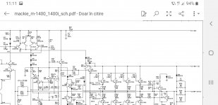
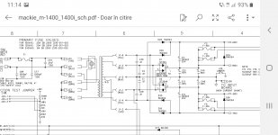
You know there's a beast outhere called Mackie, don't you?
Attachments
Last edited:
I do not recommend this implementation instead of anode of the zener on GND for a high quality amplifier. It's ok for PRO and PA but not for audiophile amplifier.

- Home
- Amplifiers
- Solid State
- SARA-2016