yes each module is a channelEach module is one channel, right ?
Then you don't need to bond thermally between them.yes each module is a channel
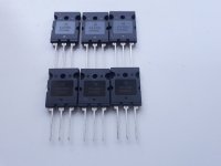
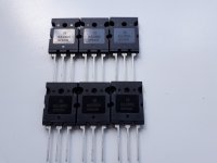
SARA 2016 RaimondAudio amplifiers are still small and ready, I don't know how to replace the 2SC4793,2SA1837 transistors with MJE15032G, MJE15033G, will there be a difference in sound?
Attachments
-
 20220621_135740.jpg561.6 KB · Views: 256
 -
 20220621_135751.jpg543.8 KB · Views: 248
 -
 20220621_135851.jpg556 KB · Views: 209
 -
 20220621_135854.jpg603.4 KB · Views: 203
 -
 20220621_135910.jpg508 KB · Views: 217
 -
 20220621_135943.jpg418.1 KB · Views: 215
 -
 20220621_140020.jpg435.3 KB · Views: 260
 -
 20220621_141728.jpg262.3 KB · Views: 249
 -
 20220621_145025.jpg281.5 KB · Views: 272
SARA 2016 RaimondAudio amplifiers are still small and ready, I don't know how to replace the 2SC4793,2SA1837 transistors with MJE15032G, MJE15033G, will there be a difference in sound?
You can use MJE 15032/3 instead of 2SA..2SC.... The sound will be the same, excellent. You must put insulation between the heatsink and the MJE's transistors.
Thank youYou can use MJE 15032/3 instead of 2SA..2SC.... The sound will be the same, excellent. You must put insulation between the heatsink and the MJE's transistors.
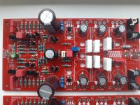
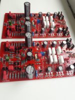
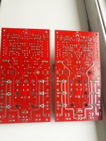
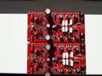
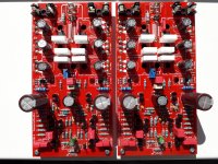
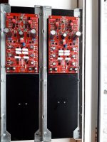
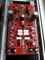
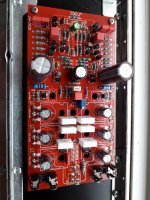
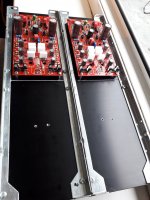
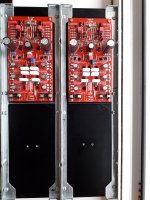
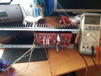
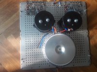
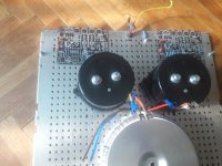
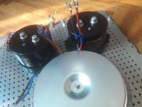
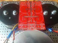
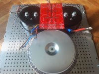
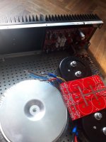
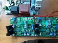
I have finished mounting the components on the boards and radiators, the power supply of the amplifiers will be ± 56V, I will adjust the bias adjustment to 15mv, now I hope the radiators will cool down well, I put thermo paste between the radiators
Attachments
-
 20220622_165457.jpg495.9 KB · Views: 163
 -
 20220622_165544.jpg615 KB · Views: 164
 -
 20220622_165617.jpg639.3 KB · Views: 158
 -
 20220622_170021.jpg493.9 KB · Views: 157
 -
 20220622_170034.jpg476.8 KB · Views: 173
 -
 20220623_072814.jpg569.1 KB · Views: 154
 -
 20220623_072827.jpg496.9 KB · Views: 164
 -
 20220623_072835.jpg574.8 KB · Views: 154
 -
 20220623_072841.jpg529.2 KB · Views: 143
 -
 20220623_072848.jpg519.3 KB · Views: 146
 -
 20220623_072855.jpg555 KB · Views: 144
 -
 20220623_072904.jpg551.5 KB · Views: 146
 -
 20220623_072910.jpg497.7 KB · Views: 139
 -
 20220623_072917.jpg587.2 KB · Views: 138
 -
 20220623_072946.jpg409.2 KB · Views: 148
 -
 20220623_072959.jpg497 KB · Views: 161

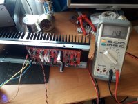
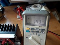
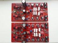
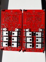
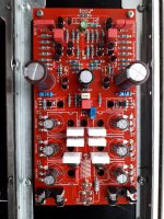
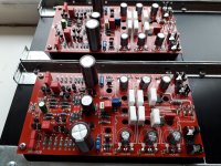
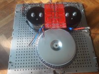
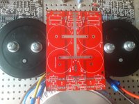
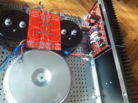
The second polarization adjustment amplifier of 15 mv, offset of 4 mv, I really like this amplifier because it is stable, a very good dynamic watercolor sound and good sound, thanks "
greierasul
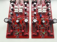
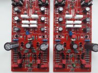
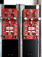
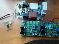
" for what you have done, I have built I made "SARA 2016 high slew rate 80V / dry" ,,, I also saw "SARA 2016 moderate speed" (there is a big difference between SARA 2016 high slew rate 80V / dry and SARA 2016 moderate speed) now follows the mounting of the amplifiers in the housing , I will have a problem with the power supply of the amplifiers I want on a wiring all the source parts with diodes VS-HFA25TB60-M3 VISHAY, but the Mundorf MLytic HC 47,000 uF 80V Power Cap capacitors have screw, can they connect wires directly to the capacitors to the wiring?Attachments

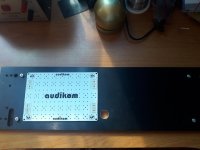
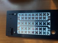
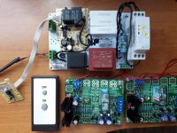
On the front you will be turned off the remote control and softstart, and of course the motherboard of the amplifiers,,,,
Attachments
-
 20220628_171840.jpg272.3 KB · Views: 147
 -
 20220628_171857.jpg250.7 KB · Views: 154
 -
 20220628_171900.jpg267.2 KB · Views: 141
 -
 20220628_171937.jpg352.1 KB · Views: 145
 -
 20220628_175956.jpg392.2 KB · Views: 140
 -
 20220628_175959.jpg340.6 KB · Views: 142
 -
 20220628_180003.jpg366.4 KB · Views: 140
 -
 20220628_180006.jpg358.9 KB · Views: 160
 -
 20220628_180026.jpg352.5 KB · Views: 145
 -
 20220628_180032.jpg360 KB · Views: 142
 -
 20220628_180039.jpg291.8 KB · Views: 137
 -
 20220628_180258.jpg415.8 KB · Views: 148
 -
 20220628_180304.jpg456.3 KB · Views: 143
 -
 20220628_180308.jpg407.4 KB · Views: 141
 -
 20220628_180316.jpg391.8 KB · Views: 146
 -
 20220628_180322.jpg327.8 KB · Views: 139
 -
 20220628_180326.jpg434.3 KB · Views: 134
 -
 20220628_181112.jpg472.3 KB · Views: 142
 -
 20220628_181118.jpg394.8 KB · Views: 141
 -
 20220628_181122.jpg432.8 KB · Views: 154
That are for a Reed relay that can be used for "mute function".
The PCB can be used without this function.
The PCB can be used without this function.
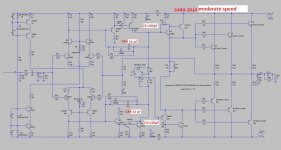
You can remove at all "REED NC" and "MUTE", do not touch them. You can use "SARA-2016 moderate speed" schematicWhat are REED NC and MUTE locations used for?
Is there a posted schematic that matches this SARA 2016 pcb layout?
Thanks!
Attachments
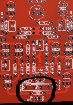
If someone has difficult speakers with small and heavy bass speakers and many in parallel, low impedance, he can permanently remove the R45 and R47 resistors. In this way the amplifier will have the maximum gain in the open loop in the low frequency area. So the control of the bass speakers will be the best. Damping factor at low frequencies will be maximum.
If you have an "easy" loadspeakers, with high impedance, over 6 ohm for example, loadspeakers good for tube amps, then do not touch R45 and R47.
If you have an intermediate speaker, not too heavy, not too light impedance, then you can choose R45 and R47 anything between 200k ohm and 1M ohm.
If you have an "easy" loadspeakers, with high impedance, over 6 ohm for example, loadspeakers good for tube amps, then do not touch R45 and R47.
If you have an intermediate speaker, not too heavy, not too light impedance, then you can choose R45 and R47 anything between 200k ohm and 1M ohm.
Attachments
I want to replace R40 and R41 with CRD diode and resistor. what is the optimal current or what diode and resistor do you recommend to use.
thank you
thank you
The current through R40, R41 is approx. 2.2mA. It could be 1n5306 instead of the zener diodes. You do not need to chance or remove R40 and R41.
I'm sorry to insist, but I'm stuck. the change r40 and 41 with CRD I read in post 67 .I refer to this .if possible more explicit.The current through R40, R41 is approx. 2.2mA. It could be 1n5306 instead of the zener diodes. You do not need to chance or remove R40 and R41.
thank you in advance
You can choose any option. You can remove R40 and R41and put the CRD's or you can remove the zener's and put the CRD's. If you put the CRD's instead of zener's, then you will have only 10v over CRD and a smaller power dissipated.I'm sorry to insist, but I'm stuck. the change r40 and 41 with CRD I read in post 67 .I refer to this .if possible more explicit.
thank you in advance
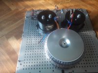
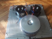
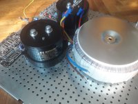
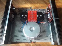
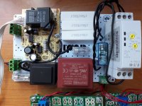
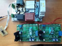
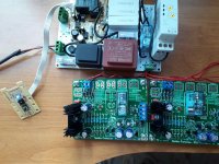
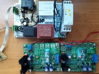
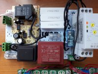
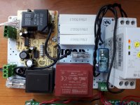
We have completed the start, stop of the button or remote control (separate transformer) and adjustable softstart (16A relay) from 0.5 sec - 1h, transformer power protection, now check their start stop, check speaker protection before being mounted in the station ,,,,,
Attachments
-
 20220713_184553.jpg443 KB · Views: 166
 -
 20220713_184559.jpg584.9 KB · Views: 168
 -
 20220713_184611.jpg547.2 KB · Views: 161
 -
 20220713_184630.jpg631.2 KB · Views: 152
 -
 20220713_184634.jpg601 KB · Views: 142
 -
 20220713_184641.jpg451.2 KB · Views: 152
 -
 20220713_184651.jpg509.6 KB · Views: 134
 -
 20220713_184732.jpg397.6 KB · Views: 135
 -
 20220713_185100.jpg522.9 KB · Views: 156
- Home
- Amplifiers
- Solid State
- SARA-2016