Monitor the pins on the MPX chip. You should see a 76 KHz oscillation, if not (and you have audio), look for a transistor shorting it to ground. If signal strength is weak, or the centre tune voltage os off, it will kill the pilot.
I'd have to examine the manual to be specific, but in general that is how it works.
I'd have to examine the manual to be specific, but in general that is how it works.
Thanks for the info, I'll try to get to it,, have to get back in it slowly,,, as I am reading notes and trying see where I left off... In the meantime the manual trouble shooting guide has me sifting thru caps on the boards I mentioned above... The lytics are first, and they seem to all need changing so far,,, Its going slow as I'm having a hard time IDing them on the trace side of the board and test the receiver after each change... Don't want to cause more problems!!!
What I would do now is stop replacing crap.
Measure what signals you have and follow the evidence. Once you have it running, then mess around with other things.
Measure what signals you have and follow the evidence. Once you have it running, then mess around with other things.
That would be the way to go but I'm still waiting of on my buddy and his test gear for help with proper measurements!

I found a reference to 67KHz (L401) and 71KHz (L402) on the Block Diagram and schematic... No reference to 76KHz tho,,,
Will look for them on the MPX board...
Will look for them on the MPX board...
67 KHz is the old SCA broadcast sub-carrier for things like store music you used to hear. 71 KHz helps reduce the amplitude so it doesn't beat with the 76 KHz oscillator. The 76 KHz oscillator will be found on the MPX board, either that or you will find a 19 Khz filtered amp, followed by a frequency doubler to 38 KHz. That is used to demodulate the stereo signal (L-R). The L-R information is on a 38 KHz sub-carrier.
It seems to have this on the schem also...19 Khz filtered amp, followed by a frequency doubler to 38 KHz.
I think I found teh 19KHz signal before ,,, couldn't get teh 38KHz tho,, IIRC.. I'll wait for my buddy and his gear.. He's got a nice frequency counter, so it will help...
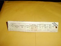
I found a voltage problem while testing the stereo indicator board, that lights the lamp... TR503, the one Hugo sent me, that got damaged, and I replaced with an NOS sub with the same or better specs... Schem calls for E-2.25V (or 22.5V) as printing is blurry and C-21V,,, with no value for B.... With the sub in place, E-20.5,, B-20.5,, C-4.8 to 5. V... Seemed to me it "could" be in backwards,, so I pulled it to test and it tests as new... So read the traces and found E-20.7,,, B-20.6 C- 0... That's with FM/MPX selected but play in mono,,, and the bulb trying to light...
Pic of sub compared to original values...
Thanks
Pic of sub compared to original values...
Thanks
Attachments
It is either off or partially on. Measure e-b voltages directly. It looks like it is in correctly from your measurements.
Thanks,,, I pulled it, tested it and confirmed it was a good TR, and reinstalled correctly... still acts as it did,,, Just read E and B each to ground E 20.5 and B 20.5 V
Update,,, Test results from post #99...
My buddy put a 19KHz signal in the receiver and measured it on a nice frequency counter,,, It was fluctuating between 18.3 down to 14.5KHz,,, I pulled C410 to measure and it is dead on 1700pf,,, There is no short in C411 and C412, and C413 are not open...TR403 reads C20.8v,,, B20.6v,,, E20.8v,,, I pulled TR403 to test it and it seemed to be intermittent,, It is a new TR that I replaced a while ago when I found the original bad,,, if this one is now bad also, there is probably a reason... I returned it to the ckt as I dont have another new one,,,
Sorry it took so long to get back to this,, I had to wait for test gear and help!! Seems my buddy's signal generator isn't stereo as I thought it was,,, he used it to align an early Scott stereo receiver that worked with AM on one channel and FM on the other,,
Not real MPX I guess!
Hi John,
Okay, how was the 19 KHz put in?
The spec is 9% modulation, 100 % being 75 KHz deviation. Your MPX filters out the 19 KHz and amplifies it, then doubles it and uses that to switch between subcarrier (@38 KHz) and the main transmission. So if your oscillator is stable, the frequency counter would be rock steady. The only reasons to get an unstable display is excessive noise, or a low amplitude signal the counter can't lock onto.
I used my counter connected to the Y1 output on the oscilloscope. Two reasons. One, the scope will amplify the signal. Two, you can see how clean the signal is. There isn't any point in trying to measure a very noisy signal.
Normally the first coil is tuned for maximum amplitude at 19 KHz. The 38 KHz coil is tuned the same way for maximum 38 KHz, there is a full wave rectifier to double the frequency. I haven't look at the manual for a while, but I can once you confirm exactly what you're doing, and also look to see what the signal looks like. You typically use a frequency counter on a VCO when receiving an FM signal with no pilot (mono). In your set, the frequency will be whatever you are modulating the carrier with, but filtered for 19 KHz.
-Chris
Hi Chris,,
Signal was put in thru a .02 ceramic cap into TP201,,,, We did not attempt to adjust any cans just wanted to see if 19KHz was there,,. I will ask him to take a look your post and try to answer you... He is starting a new job next week so there may be a delay,,,
Signal was put in thru a .02 ceramic cap into TP201,,,, We did not attempt to adjust any cans just wanted to see if 19KHz was there,,. I will ask him to take a look your post and try to answer you... He is starting a new job next week so there may be a delay,,,
TP44 is the MPX input, C401. TP202 is the detected FM audio, so possible there also.
If you are not receiving a good FM signal on the antenna inputs, the MPX circuit will probably be disabled. So the easiest thing is to transmit an FM signal, tune to it and modulate the FM generator with a 19 KHz signal. Make sure the FM generator doesn't filter this out. Doing it this way makes certain the MPX isn't disabled and you can monitor the test points (202 and 44) for that signal. For a sanity check, you an also change to 400 Hz or 1 KHz and look for those signals also.
If you are not receiving a good FM signal on the antenna inputs, the MPX circuit will probably be disabled. So the easiest thing is to transmit an FM signal, tune to it and modulate the FM generator with a 19 KHz signal. Make sure the FM generator doesn't filter this out. Doing it this way makes certain the MPX isn't disabled and you can monitor the test points (202 and 44) for that signal. For a sanity check, you an also change to 400 Hz or 1 KHz and look for those signals also.
- Home
- Amplifiers
- Solid State
- Sansui 400...