I'll scan it once i have time. I'm working on a disaster that is due tomorrow (was today). I've been on it for over 6 days now.
Your meter will probably read okay with this test. Certainly much more useful than resistance checks will ever be. Try and stick it together. Battery holder and a resistor plus wires. No sweat.
Your meter will probably read okay with this test. Certainly much more useful than resistance checks will ever be. Try and stick it together. Battery holder and a resistor plus wires. No sweat.
Really dont bother,,, my buddy got his Scott done so maybe he'll have some time to give me a hand with meters and other test gear,,, I guess I do OK with tubes because the meters are close enough for 4-500VDC, but not 5-20VDC!!!
I'll get this sorted sooner or later,,,
Thanks,,,
I'll get this sorted sooner or later,,,
Thanks,,,
No probs. I'm here.
One thing about tube circuits. Loading. Your meter can significantly change the circuit voltage depending on impedance and your input resistance and capacitance.
I service and design tube equipment also.
What we used back in the day was what was available. I still have my Heathkit IM-18 I built (still works fine), and I have others. They have their place. I do have and use a Simpson 260 6P. It is an average responding meter, so modern rms responding meters do not correlate on AC. To match the readings in old service information you need the older instrument. But, if you want to really know what a circuit is doing, you pretty much have to use a modern, high quality meter. Plus, I really do not trust cheap meters with my safety at higher voltages. I also have high voltage probes.
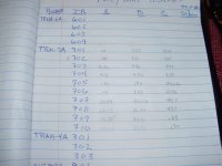
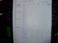
My buddy came over with a Fluke 87III, and we took and confirmed some transistor readings on FM/MPX/amp related boards...
I hope these give a better overview of what's going on in the Sansui,,,
Reading's in parenthesis are with a signal on the indicator light board,, others are with no signal... I took readings on all three leads of the transistors, but a lot of them aren't on the schematic....
Thanks...
I hope these give a better overview of what's going on in the Sansui,,,
Reading's in parenthesis are with a signal on the indicator light board,, others are with no signal... I took readings on all three leads of the transistors, but a lot of them aren't on the schematic....
Thanks...
Attachments
Okay, try this. Measure emitter - base and simply note if the transistor is biased on or not. Also measure emitter - collector voltages. This may give you a clear picture. I don't have time to transfer your readings to a schematic to troubleshoot - sorry.
Using the diode test feature, measure the two junctions in each suspect transistor.
The voltage difference between the emitter and base of Ge transistors will only be 200 to 300 mV. Measuring from common ground the applied voltages will be much higher. So measurement error and noise can swamp accurate readings. So use the emitter of the part as a reference, that will tell you what the transistor "sees" more accurately. You can't do that in RF circuits, then we normally use an oscilloscope as the capacitance from wires and the instrument will upset the circuit. You can measure junction leakage with a careful setup. A 3458A would be sensitive enough to read directly - as is my 34465A. However, the IT-18 is cheaper and faster, so that is what I use. With Ge transistors and diodes, you do need to look at leakage as well.
Anyway, trying to troubleshoot remotely this way is ineffective unless the readings are taken in away that you can absolutely count on them. The greatest amount of time in a repair is the troubleshooting and discovering and following the clues. So unless the clues are clear and guaranteed to be correct, you are wasting your time.
So we need junction voltages using the emitter as the reference, and suspect parts need to be removed (and new, replacement parts) and confirmed to be good without a doubt. As a young technician I learned the hard way, Ge parts in new packages can be bad. I was in the practice of poking the leads out of the bag and measuring them before removing them from the store. I rejected a lot of parts. That dropped my aggravation with repairs quite a lot. I confirm light bulbs, transistors and capacitors are good even today, and match resistors (thereby checking them also). Ever try to troubleshoot a bad "new" part? It's pure loss, and very difficult.
-Chris
Hi Chris,,
I can add the schematic values to the readings I took if will help decipher them, however many readings aren't on the schem,
I can measure E to B and E to C, if that will work better with the diode feature I can do that also...
I realize you are spending a lot of your time helping me, and I appreciate it,,, and am sorry I haven't taken readings right, but I will try again and continue to look for an IT-18 to test the transistors so they can be evaluated them,, I have a lot of Ge transistors that I got last week, and according to spec sheets I may have most I need for this receiver, which is also a major part in repairing this guy,, as long as they test good...
Understanding the test results is most important part...
Thanks again for the time and explanation,,,
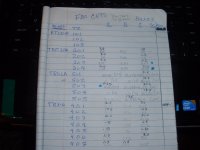
PS,,, Here are the available schem readings for FM boards... Dots are next to readings that seem very wrong...
John
I can add the schematic values to the readings I took if will help decipher them, however many readings aren't on the schem,
I can measure E to B and E to C, if that will work better with the diode feature I can do that also...
I realize you are spending a lot of your time helping me, and I appreciate it,,, and am sorry I haven't taken readings right, but I will try again and continue to look for an IT-18 to test the transistors so they can be evaluated them,, I have a lot of Ge transistors that I got last week, and according to spec sheets I may have most I need for this receiver, which is also a major part in repairing this guy,, as long as they test good...
Understanding the test results is most important part...
Thanks again for the time and explanation,,,
PS,,, Here are the available schem readings for FM boards... Dots are next to readings that seem very wrong...
John
Hi John,
No problem. Education is the most important thing, getting it repaired properly is the next. I just happen to have some very pressing things to deal with lately.
There isn't an attachment to look at.
Do your voltage readings from emitter to base and emitter to collector. This isn't always normal but in this instance it would help.
The diode test is done with the circuit unpowered (off) and discharged. This is a good place to start. Keep in mind that any and all in-circuit tests are done with whatever else in parallel with the junction you are testing. So if you run into a reading that doesn't look right, remove the component and test it out of circuit.
I just had a circuit where a transistor measured short emitter - base. Removed the part, it was fine. Removed a capacitor in parallel, it was fine. O found a solder short elsewhere on the PCB. Technician induced malfunction. (TIM). This just illustrated a few things. You can't make assumptions and some tests are not accurate the way they were executed. Also it shows how important your workmanship is.
When you are troubleshooting I find one difficult thing for people to do is to separate observations (facts) from conclusions (assumptions quite often). Failure to work on pure factual evidence will often lead you in the wrong direction. That is the difference between something that is "unrepairable" and a well done job.
-Chris
Last edited:
Hi Chris,
I forgot to include the schem readings...
I understand troubleshooting, you showed me I just dont have the proper tools to do this kind of troubleshooting properly,,, and I'm working on that problem... We calibrated a VTVM I rebuilt with my friends Fluke while he was here, and its been holding rock steady ever since,,, so I can use that til something better comes along..
I don't expect you to ever drop your work for this, as I appreciate your help!!!!!! I'll just add to the thread as I think something is relevant,,,
Thanks again,
John
Attachments
Hi John,
That's cool, no problem at all. I am hoping others get something from this.
Your VTVM is excellent for working with tube equipment. I used one for many years as a youngster, and still did occasionally until I got a FET meter, then waited until DVMs got better. But using a VTVM on this stuff can sometimes be frustrating. I am extremely pleased you got the VTVM calibrated. Did you calibrate each range, or just the factory procedure? The divider is probably out back and forth for your ranges. It wouldn't hurt to replace the divider resistors with 0.1% units. Watch the voltage ratings on these! Putting some in series is a valid way to increase the breakdown voltage rating - this is not the same as power dissipation. Read the datasheets for the resistors before choosing them. Also pay attention to the temperature coefficient, you want the lowest you can get or when measuring near the top of the range (where you should be), you may see the indication changing. changing slowly. These resistors are the major error term and source of drift in your meter.
Doing this will greatly enhance - improve your VTVM.
-Chris
A quick look shows some transistors may be reverse biased. I'd have to really look at the schematic. Otherwise they are open emitter - base.
Thanks,,
VTVM is a Triplett 850,,, I rebuilt it a while ago with 1% resistors,,, used it when it was first done then let it sit,,, DMMs seemed easier and didn't need to warm up!!! I left this one on for a few days and it stayed on zero, DC+ range,,, which is mostly what I use it for... Calibrated each DC range, it has separate pots for 3 DCV ranges IIRC.. Not too interested in ohms on this, as I have a Fluke and use it for ohms only,,, Yep,, resistors in series is a good Voltage trick!
OK,, No hurry on the Sui,,, I think this was a tough rebuild choice for a first FM/MPX project, but it found me,, I wasn't looking for it!!! I appreciate you looking into it...
Hi John,
Sounds good. I'll have to look the meter up later, but it sounds familiar.
As long as you used good 1% resistors, you'll be fine. Meter movements are typically 2.5% near the top of the scale and can be up to 33% off near the bottom. You need to characterize your meter using the 87 yourself just so you know what corrections you need.
Yes, its basically the same as RCA voltohmyst,, it can use the same probes, and same size meter, so even I can read it! You have to use the right range so you are reading past half the meter... I left it on overnight and it was still zeroed in the morning!! I tried to match the diodes/triodes in the tubes when I took it of the shelf! I'm thinking thats what was used when the Sansui was new(1967)?? they didn't have DMMs back then...
They were all the same basic circuit. Some used better meter movements and had better layouts and power supplies.
I can assure you that in 1967, a DVM was a lab thing. Service people used VTVMs up well into the 1970's and even the 1980's for the old guys. I remember them specifying a DVM early on, specifically to force some shops into updating. My Simpson 260 is still used, but for specific things. Solid state "VTVMs" were a big thing, solid state "12AU7A tubes". I updated and calibrated a few for friends. Instant on was nice, and much lower drift.
I can assure you that in 1967, a DVM was a lab thing. Service people used VTVMs up well into the 1970's and even the 1980's for the old guys. I remember them specifying a DVM early on, specifically to force some shops into updating. My Simpson 260 is still used, but for specific things. Solid state "VTVMs" were a big thing, solid state "12AU7A tubes". I updated and calibrated a few for friends. Instant on was nice, and much lower drift.
Yes,, teh schems look very similar even teh tubes,,, my buddy has the RCA,,, and we compared them... I took a HVAC correspondence course when I was inneth Navy, just liked to learn anything mechanical! One of the lessons/projects was building a VTVM kit,,l I still have it but 50-60 years dint age it well!!! I dug it out again also, and a wafer on the range switch was broken,,, I tried to replace it but it was a fools errand!!! I did get teh DCV and ACV to read somewhat, but couldn't come close to calibrating it even after replacing all teh corroded pots!! It was an odd duck, and used a 6.8K probe... to test it as it was built you used a 1.5V battery and a neon tester!!!
Yeah, if they break your only hope is Epoxy - or a new switch. You could always make a relay PCB assy, but that's a bit much.
The 1.5 V battery was very commonly used to calibrate the meter. I've never heard of a 6K8 probe, that's very low!
The 1.5 V battery was very commonly used to calibrate the meter. I've never heard of a 6K8 probe, that's very low!
- Home
- Amplifiers
- Solid State
- Sansui 400...