Just measured the current consumption while hooked up to the UBIB: 72 mA from the positive reg, leds remain off... This whilst with the 75 Ohm static load the leds where on...
Transformer used is a toroidy audio grade with dual 15v secondaries, so that should be good.
Transformer used is a toroidy audio grade with dual 15v secondaries, so that should be good.
Last edited:
When you connect + & - from the Ubib sections to the Mercury, do you branch out from the Ubib terminals like -< or you use a single cable out and then chaining ++ and -- at the Mercury? Prefer the -< method.
Tried both Salas, i understand -< would have the preference.
I just excluded one half of the mercury so no branching was necessary.
One DMM measuring current between UbibPosOut to MercuryPosIn --> reading only 35 mA, which is half of what it should be (Whole mercury consumes 155 mA per rail, half a mercury should do 70 to 80 mA per rail).
Second DMM measuring voltage across the Ubib Output terminals:
- Positive reg: reads +0V (without load and with static R75 load this reads +15V)
- Negative reg: reads -15V
Again, this way no branching except for the 0-terminal, which i've tried both as -< and <=
Vdrop over R1=normal (600ish mV)
Last edited:
Just a hunch here, i'm suspecting m1 and/or m2 might short circuit to the chassis. Which is extremely weird as i'm using both insulating plastic 'pads' between them and also use the screws with plastic inserts to keep the screws at a distance from the ic's.
Could that explain this behavior? If so, i could possibly not explain why the regulator would work with a fixed resistor as load.
Could that explain this behavior? If so, i could possibly not explain why the regulator would work with a fixed resistor as load.
Its a logical suspicion that the + section loses current to some kind of short due to mounting. Check continuity between mosfet metal tabs and the mounting surface. The DMM should not beep if insulation is good.
Could that explain this behavior? If so, i could possibly not explain why the regulator would work with a fixed resistor as load.
Yes, when a grounded load closes circuit to a common that a floating load does not.
Does M1 still dissipate when Vout drops to zero? That would mean there is current produced that goes somewhere. There should also be voltage across R1 if so.
I'll check and report back in an hour or two probably, had to take a business call in between 🙂
In any case thanks for all support Salas, amazing!
In any case thanks for all support Salas, amazing!
It was indeed a short, i think that one of the screw isolators touched a mosfet.
Now all plays well!
I would think the ubib provides better bass and a little more quietness than the placid hd bp reg.
Next step will be to hookup two reflektors to the avcc power inputs, but that is for a different thread!
Now all plays well!
I would think the ubib provides better bass and a little more quietness than the placid hd bp reg.
Next step will be to hookup two reflektors to the avcc power inputs, but that is for a different thread!
 Congratulations for finding the fault. Nice that you also like it. Give it some more play hours for it's electrolytics to flex.
Forgot to mention that C2 bypassing with a small film capacitor is permissible if subjectively preferred in an application. But C3 bypassing is not permissible.
Salas, when powering the AVCC side of an ES9038Pro DAC chip. Would you actually recommend a positive Ubib or a Reflektor-D? We are talking 200mA consumption so both could deal with it.
I have both so can experiment with both ;-)
I have both so can experiment with both ;-)
Last edited:
I would expect the Ubib to be more adequate for this position but better try both types to decide.
Sorry to be an annoyance, my positive UB is not outputting the correct voltage but still seems to be working on the surface, so not sure when it happened.
VRR did not fail, it is still the right value.
The voltage is not going over 10.7V with ~5k VRR, I get 8.5V at ~3.3k VRR, seems the scaling might be off rather than it being limited.
More capacitance was added to C2 lately and I removed it in case the cap had started becoming leaky for some reason but that wasnt it.
I also had been playing with super capacitors so maybe the output could have been exposed to reverse current at some point.
See if Q1 Q2 Q3 still work with correct about 0.6V Vbe and if M2 still has correct about 3-4V Vgs
Q3 and Q1 ok. M2 Vgs ok.
Q2 Vbe 0.3V... replaced and now working again!
Thank you for guidance.
The Q2 actually blew in the neg reg when I connected supercaps that werent discharged fully when it was powered off... but this pos reg still worked after that, maybe delayed effects of the damage?
I feel like you walked me through the same process of checking Vbe and Vgs to find a faulty component, is it safe to say this is a reliable method for finding faulty devices?
Maybe delayed or partial damage, yes.
Checking Vbe or Vgs is a reliable indication for finding faulty semiconductors in energized circuits. We expect them to show datasheet correct values when healthily conducting.
Checking Vbe or Vgs is a reliable indication for finding faulty semiconductors in energized circuits. We expect them to show datasheet correct values when healthily conducting.
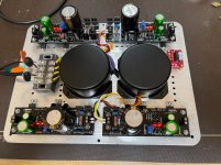
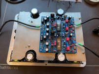
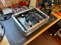
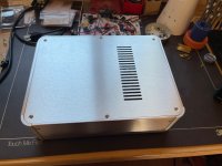
Another use for UBIB for my fully balanced Nu-Tube headphone amp. Did not listen to it yet, but believe it will be prefect match. All assy is still in progress.
Attachments
Last edited:

- Home
- Amplifiers
- Power Supplies
- Salas SSLV1.3 UltraBiB shunt regulator