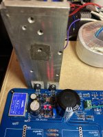
I do not have have an exact schematics for this board and al I know is from following the traces. I really regret going that way (having a board from a guy who did not provide a thematic). I did it mostly for having room to install poly caps. It looks like that DC-DC converter feeds before the regulator, right from the big C. However, it is gonna be more then 24V written on it. Well, filament voltage and current are stable ")
So I use big *** sink and the M1 M2 are barely warm, but still voltage drifts 2-3V down after 20mins. I know that it is not your layout and kinda feel bad asking it here, but anything else I can check before I go Zener option? Thank you!
Attachments
Last edited:
Yes, circa 19V Vz sounds logical. Zeners have tolerances anyway. Preferably on the plus side of 19V in this occasion if it can be hand picked. But nominal Rail voltage precision for an analog preamp is not a crucial matter I would think. Especially when for single rail circuitry. Ballpark stuff will work as good.
1N5249B-TR looks fit for the job. Needs little current as this circuit will provide it. You could also try a higher value C2 than used with the trimmer as long as it fits to can filter the lower impedance Zener better. Maybe decide C2 in the end after a comparison when the full preamp board is ready to be installed in its case.
One more thing, do you think transformer with 24V or 22V secondary would be a better option (for 24Vout and 100-150mA)?1N5249B-TR looks fit for the job. Needs little current as this circuit will provide it. You could also try a higher value C2 than used with the trimmer as long as it fits to can filter the lower impedance Zener better. Maybe decide C2 in the end after a comparison when the full preamp board is ready to be installed in its case.
Don't know if 1941's or 1921's stated power spec is average or max, that's important to be clear because we apply a constant current sourced psu here...
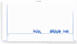
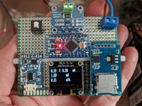
I did put together a Power Meter, it's based on the ina219 current sensor and build using this project here.
The +5v analog never exceed the 48mA while playing (I've got one spike when apply main power and one at power off)
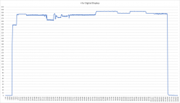
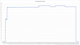
The +5v digital with the Display dsp1941 stay at 294mA. Without the Display dsp1941 it's 233mA
Hope it help.
Attachments
I've built a 3-way active crossover that uses 5 op-amps per channel, I'm using LM4562s and reading the data sheet they have a Iout of 23mA/opamp, if I was to use OPA2134s this would increase to 35mA/opamp.
Is the total 230mA (OPA2134 350mA) is split across the two positive/negative UltraBIBs or is the same for both?
I've chose a R1 of 3.3ohm for both UltraBiBs.
Many thanks.
Is the total 230mA (OPA2134 350mA) is split across the two positive/negative UltraBIBs or is the same for both?
I've chose a R1 of 3.3ohm for both UltraBiBs.
Many thanks.
Iout is usually quoted with +/- in op-amp datasheets. So its pulled as much from both rails.
In an active crossover I don't think they will ever need to push substantial output current though. They would if to drive headphones for instance. Even 2VRMS on 10K load is only +/-283uA peak. Simply add their total quiescent current spec and give a good margin on top.
In an active crossover I don't think they will ever need to push substantial output current though. They would if to drive headphones for instance. Even 2VRMS on 10K load is only +/-283uA peak. Simply add their total quiescent current spec and give a good margin on top.
- Home
- Amplifiers
- Power Supplies
- Salas SSLV1.3 UltraBiB shunt regulator