How to calculate Rf resistance?Thank you!
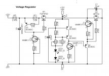
The published schematics are 100% correct. Follow them without hesitation. There are clear and adequate emitter arrows also there. If you will analyze beyond PSUs output polarities you will understand why those semiconductors polarities work that way inside the PSUs.
Rf is a small value below 1Ω to make an RC low pass EMI/RFI filter with C1. 0.33Ω or 0.47Ω is alright. There is inrush current there at power on so it better be small value and sturdy. Just to take the RFI edge off. Classic RC filter calculations apply if you want to quantify the effect. RC Low-pass Filter Design Tool
SO, VR1 resistance, if I understand it correctly, it is:
I want +15V out and the CCS is limited to about 100mA
R=Vout/A
R=15V/0.1A
R=150 ohm
No matter, I need to monitor and adjust at the same time. If anything is odd or off, please inform me - many thanks")
I want +15V out and the CCS is limited to about 100mA
R=Vout/A
R=15V/0.1A
R=150 ohm
No matter, I need to monitor and adjust at the same time. If anything is odd or off, please inform me - many thanks
Attachments
Last edited:
VR1 adjusts Vout as an I to V reference using VbeQ2/R21 ~2mA on its variable resistance for Vdrop. Leds Vf and Q2 Q3 2Vbe add to it.
About currently available batches of J113 possible IDSS and source resistor values read #1559 (also linked form the footnotes of post#1).
About currently available batches of J113 possible IDSS and source resistor values read #1559 (also linked form the footnotes of post#1).
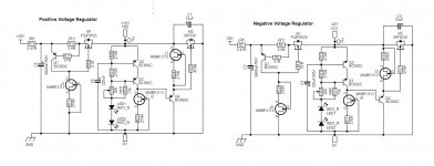
The rectifier would produce a +dc and -dc right... so that is how I was thinking. Or should the -20vdc simply be gnd ?P.S. If not a typo, don't connect any -20V to the left as shown. There's the GND.
edit
Saw just now your "there's the gnd"... will get right on it
Last edited:
It will produce a train of positive going half sinusoidal peaks in this case.The rectifier would produce a +dc and -dc right... so that is how I was thinking. Or should the -20vdc simply be gnd ?
gnd in place and for the negative version, the gnd and +vdc switch places, is that correct ?
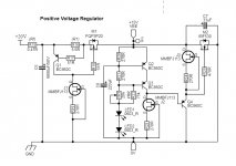
The bridge and parts inside the circuit mirror polarities for negative. The top line becomes negative in respect to bottom line GND.
I'm a total noob, so I need help.
Want to power my pi3A+/dac system with the ubib. So I will replace the general 5V/2,5A PSU. The current for usage of PI+dac is max 500mA. But I measured +/- 350mA while usage.
0. I build a positive board.
1. Is it a good calculation for R1 to go with 600mA/600=1R? Or should C1 be bigger, exspactation of smaller current.
2. C2 and C3 is clearly eyplained in BuildGuide.
3. R9 is depending of choosen/exspacted spare current. depending from choice for R1
4.Transformer. Would go for toroidal transformer 30VA with 2x9V from audiophonics. Are this values ok? Other recommendations for shop/seller in germany/europe? here are not many shops to find.
thanx in advance.
Last edited:
For PI we usually choose the L-Adapter which is linear series. Because computers have high boot peak vs average consumption. Not to set a shunt high just for boot and then it burns away too much excess.
If your Pi has 500mA peak then 1R will cover. If you will see difficulty to boot then it needs more margin. C1 can be 10000uF to avoid some vin-vout loss to peak AC ripple during boot.
9V transformer is alright for 5V in this application. Maistream toroidal like Talema etc. from EU big electronics online stockists is good for the job as well. Unless it will be too close to sensitive circuits for hum where R-Core is better.
That is an excellent question and if anyone, you deserve an answer.The schematics are already drawn in post1 and guide, why you redraw them? Which drawing software you use?
I am currently working on an updated Vacuum State Electronics RTP3D preamplifier (and later also the DPA-300B power amplifier), and the Shunt Regulator (SuperReg as VSE calls it) and the Input Signal CCS (JFet based) need some voltage regulation. The original SuperReg calls for an external one and the input signal ccs has a very simple 1 pcs MOSFET regulator. So... I looked around and discovered that the best voltage regulator on the market is your UltraBiB, so that is what I went for.
Why I am redoing the schematic, well, I also want the regulator to be physically close to the circuit it is suppose to feed, so the Shunt Regulator & CCS (separate circuits) gets one UBiB right on the PCB they will be mounted on in close proximity to reduce parasitic C and L
***
The software I am using is called EasyEDA, its basically a PCB CAD software from JLCPCB. I like it. Easy to work with, fast learning curve, online component database and there is all the tools one need to either create or modify symbols and footprint.
- Home
- Amplifiers
- Power Supplies
- Salas SSLV1.3 UltraBiB shunt regulator