They are believed to last 16000 hours at your 45C as I explained. Count your average use and project hours to years. You could set 12000 hours as your target if to be conservative.
so if it's powered on for about 2 years straight, I should replace them soon?... Or is there another sign that I should look for if I'm only looking for reasonable performance?
Thanks again!
After thousands and thousands of hours as the dissipation factor and ESR will start to change enough, the sound will become softer in contrast and less detailed. In bad wear conditions the circuit functions themselves will be affected. Maybe some noise or an instability.
Got it. I just ordered TDK B41505A6688M000 for C1, EEU-FC1J331L and EEU-FC1H101B for C2/3 per build guide. Those are rated 5000h/3000h @105C and should last for decades operating at 50/45C.
The caps all look fine externally and the C1 are actually rated for 2000h@85c, so those have at least a couple of years left. I'll keep the replacements handy but will probably put off installing them until I get more time on my hands. The UltraBib is very tightly installed in my build and I don't want to risk breaking things at the moment...
It's not an easy feeling knowing that c2/3 might "expire" in the coming months. Can't say it helps that there is no definitive reason to believe that it won't matter. But I suppose I'll be fine
Salas, I know the ultrabib instructions suggest 9v secondaries to power ultrabibs at 5-7v or so and then 12v for 8-10vout. I have two types of regulators I may run on my DACs AVCC lines. One is better fed by 9v and the other closer to 5v. Is there any harm in feeding the ultrabibs 12v secondafies even if they’re only set to 5v? I may get custom transformers and want them to be as versatile as possible.
Salas, I know the ultrabib instructions suggest 9v secondaries to power ultrabibs at 5-7v or so and then 12v for 8-10vout. I have two types of regulators I may run on my DACs AVCC lines. One is better fed by 9v and the other closer to 5v. Is there any harm in feeding the ultrabibs 12v secondafies even if they’re only set to 5v? I may get custom transformers and want them to be as versatile as possible.
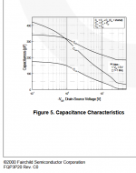
No electrical harm, just more M1 dissipation. As a matter of fact with more Vin-Vout DC difference less internal capacitance is created in any Mosfet. In other words M1 becomes faster. This beneficial effect levels out at about 25V across M1. Max pF are already halved at 5V difference. The good side effect continues for bit more open HF to feel better about the extra dissipation.
Attachments
Salas, I know the ultrabib instructions suggest 9v secondaries to power ultrabibs at 5-7v or so and then 12v for 8-10vout. I have two types of regulators I may run on my DACs AVCC lines. One is better fed by 9v and the other closer to 5v. Is there any harm in feeding the ultrabibs 12v secondafies even if they’re only set to 5v? I may get custom transformers and want them to be as versatile as possible.
No, in fact more input voltage headroom should be benefitial for the regulator's performance, but beware M1 dissipation increases.
edit - ... ah already answered, nevermind
Salas I am using UBib (not the GB boards, but layout is pretty much identical) to power Korg B1 and the voltage drift quite a bit while it warms up. It starts at 29 and then drifts to 23.8. That looks a little bit too much. Anything I can test? I am using transformer with 24V secondary to get 24V regulated. If I use variac and do 22V to 24V I get basically the same. I was hoping that lowering input voltage will produce less heat and less drift...
Yes it is too much for that voltage range. Not its usual drift. If its simply a matter of location and much radiated heat delta to the BC560C transistors area there are two basic ways to change that exposure. Either to create less heat (by less CCS/less Vin-Vout and/or bigger sinks) or to ventilate it better.
An alternative drastic approach for difficult circumstances is substituting a Zener in place of the voltage trimmer. Its described in the build guide.
An alternative drastic approach for difficult circumstances is substituting a Zener in place of the voltage trimmer. Its described in the build guide.

Nice looking complex board. What is the canned buck converter for? Relays?
You basically remove the VR1 trimmer and Vrr. You install a half Watt Zener in Vrr's place. You use one with roughly 4.6V less Vz than your target Vout. About details of orientation etc. see the guide's notes section.
You basically remove the VR1 trimmer and Vrr. You install a half Watt Zener in Vrr's place. You use one with roughly 4.6V less Vz than your target Vout. About details of orientation etc. see the guide's notes section.
Thats for powering filaments of that Korg nutube. I will read that guide section as I definitely skipped it So if I go with let say 19.25V(for a target 24V), does this mean the voltage will not be adjustable and may not be 24V in the end, so it is iterative process. I am just thinking how many different Zener's to buy
So if I go with let say 19.25V(for a target 24V), does this mean the voltage will not be adjustable and may not be 24V in the end, so it is iterative process. I am just thinking how many different Zener's to buy
Last edited:
- Home
- Amplifiers
- Power Supplies
- Salas SSLV1.3 UltraBiB shunt regulator