C1 value
I wonder if I could use 3300uf or 4700uF for C1 as I already have these in my possession. Thanks.
I wonder if I could use 3300uf or 4700uF for C1 as I already have these in my possession. Thanks.
Last edited:
Salas,
I've just built +Ultra BIB using the standard BOM parts. Everything lights up but the output voltage is fixed irrespective of trim pot adjustment. Any quick suggestions before I delve in?
I've just built +Ultra BIB using the standard BOM parts. Everything lights up but the output voltage is fixed irrespective of trim pot adjustment. Any quick suggestions before I delve in?
Yup, same voltage as I measure out of the back of R1. I've checked the pcb, no solder shorts on either side. When i add a load the voltage drops, and the leds run dimmed.
M2 never warms up, likely culprit?
M2 never warms up, likely culprit?
First verify that Q2 & Q3 are PNP (BC560C in +PS) and correctly oriented. There should be 0.61-0.63V across each R5 and R6 for the Vref to work normally. Verify all semis for type and orientation anyway. Including the MOSFETS.
Yup, same voltage as I measure out of the back of R1.
Is there near 0.6V drop across R1's legs by the way?
You should check there is normal Vgs in all MOSFETs, normal Vbe in all BJTs, and circa 2mA indicating drops across all 270R resistors. Also if you put 20K VR1 it may take many anticlockwise turns to initially bring Vout below the rectified DC level when aiming at a low Vout setting.
Hey Nick,
Id like to go to 48v on the BiB. Caps and fets should be fine as they are BOM. Can I do this?
Cheers,
Greg
Id like to go to 48v on the BiB. Caps and fets should be fine as they are BOM. Can I do this?
Cheers,
Greg
Hey Nick,
Id like to go to 48v on the BiB. Caps and fets should be fine as they are BOM. Can I do this?
Cheers,
Greg
No because J1 and J3 will go 10V and 5V beyond their 40V max spec and Q3 will be right on its 45V max (Vceo). Maybe it can be done with modifications.
 Which one was the bad part?
Extended max Vout mods
I thought of the higher than standard max output voltage capability modifications for Greg 🙂
1. CRD diodes Semitec E-501 (100V 300mW 0.5mA current regulative diodes) instead of J1 J3. Soldered from drain pad to gate pad replacing those two PF5102. CRD's cathode goes to gate pad is the orientation. R4 & R8 may remain as they will be skipped out of circuit by that action anyway.
2. BC556C BC546C (and B) instead of BC560C BC550C for Q3s
3. 470R instead of 270R for R5 R6. 330R instead of 270R for R7
4. 50K VR1 330K VRR instead of 20K 75K respectively
The above modifications should allow for 5V to 65V adjustable Vout range. Or 5V to 50V if VRR is 100K. Watch the capacitors DCV spec regarding the new higher AC Tx secondaries and new higher Vout range, also remember that the M2 MOSFET will dissipate more as the output voltage goes higher.
i spent 250 dollars on a new soldering station that can heat the tip to 425 C and the same thing happened. anpther board and another sert of compoenets runined. for me it is impossible to desolder from these boards.
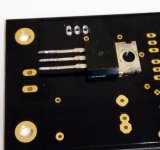
You got me worried and I just performed a desoldering test. Not the easiest board I agree, it took some time, but I managed. With an 80 Euro desoldering station gun (ZD-915) in bad enough back-filter and nozzle state. I also used the cheapest greyer leaded 0.5mm solder wire I had around. It wasn't flowing too well during the soldering phase under my 90W Oki/Metcal iron... Just tried to make the situation worst possible.
Attachments


i dont know. im not faulting the product. i know it is my problem but i have tired everything i could, i ruined one positive board. oredered all compoents, bought a newe soldering station weller WD1 and then ruined the second positive board and im not even gonna bother trying the remove the components again. the transitory just never come out. the caps are the only ones that i can remove. all resistors are very difficult too. im just so frustrated.
Last edited:
Use a dim bulb tester next time you power up. Although you won't repeat such a big electrical mistake as having both rails MOSFETS non insulated on a common sink, you never know what can go wrong next. Leave it aside for a while, build a bulb tester. When the frustration will go away try again. Money on a good iron like a Weller WD1 is money well spent anyway.
P.S.
Pick each leg of a resistor with long nose pliers from the upper side and pull as you heat up the pad on the bottom side. Clear the holes in the end with a sucking tool.
P.S.
Pick each leg of a resistor with long nose pliers from the upper side and pull as you heat up the pad on the bottom side. Clear the holes in the end with a sucking tool.
Dadbeh, I didn't read the backstory, but Salas is using a desoldering station with vacuum and you are using a very nice soldering station. Desoldering with braid, etc. on thick PCBs with heavy ground planes is never easy and risks the board. A desoldering gun/station makes ALL the difference! My Haako desoldering gun is invaluable for the rare times I need it. I never really mastered desoldering braid + soldering iron - too many lifted pads. With the desoldering gun component removal is a 30 second, no stress affair with a 100% certain outcome.
BK
BK
Dadbeh, I didn't read the backstory, but Salas is using a desoldering station with vacuum and you are using a very nice soldering station. Desoldering with braid, etc. on thick PCBs with heavy ground planes is never easy and risks the board. A desoldering gun/station makes ALL the difference! My Haako desoldering gun is invaluable for the rare times I need it. I never really mastered desoldering braid + soldering iron - too many lifted pads. With the desoldering gun component removal is a 30 second, no stress affair with a 100% certain outcome.
BK
thanks man. i looked it up it is 300 bucks. i can not afford it.
- Home
- Amplifiers
- Power Supplies
- Salas SSLV1.3 UltraBiB shunt regulator