Any IDSS values either below or up to about 10mA will be drop in compatible. Will not ask for associated resistors value changes in the circuit.
Thanks Salas. Fair, I "Will not ask", but if you give training, please put me in the list! Two weeks in Greece!😀🙄
May be I will buy the Jfet matcher kit and study a litle bit about matching. The kit manual may suffice for a start.
Wrong R-core followup
Hi here 🙂
As a followup on my quistion regarding the use of "centertapped" transformer some pages back, just want to tell you that the shop "Audiophonics" is a very good trusted dealer, as they sent me a new dual secondary (torrid this time) for free; not even asking for money or return...
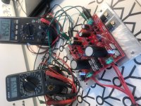
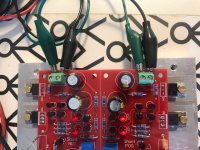
In meantime i recieved my board's... (aka' homemade)
I stuffed them with parts i allready had at home, and vupti... working and rock steady.
I had some resistors, giving me 200Ma & 160mA for testing (R1 + R1n), if i load with a testload around 130mA they are still giving the same voltage... perfect!
The C3 resistor is Panasonic 100uF / 50v, the C2 is (for me at least) unknown brand at 330uF / 50v... When i order some parts for my other project's i will ofcause order the right parts + 3ohm resistors for R1+R1n... but just had to see it working today 🙂
I also need ~15,5v out, but i had to solderin some 5k trimmers i had, they will also be swapped into 10k's i think. - The highest voltage i get with 5k trimmers is around 15,2vdc +/-
Rgds; Jesper.
Hi here 🙂
As a followup on my quistion regarding the use of "centertapped" transformer some pages back, just want to tell you that the shop "Audiophonics" is a very good trusted dealer, as they sent me a new dual secondary (torrid this time) for free; not even asking for money or return...
In meantime i recieved my board's... (aka' homemade)
I stuffed them with parts i allready had at home, and vupti... working and rock steady.
I had some resistors, giving me 200Ma & 160mA for testing (R1 + R1n), if i load with a testload around 130mA they are still giving the same voltage... perfect!
The C3 resistor is Panasonic 100uF / 50v, the C2 is (for me at least) unknown brand at 330uF / 50v... When i order some parts for my other project's i will ofcause order the right parts + 3ohm resistors for R1+R1n... but just had to see it working today 🙂
I also need ~15,5v out, but i had to solderin some 5k trimmers i had, they will also be swapped into 10k's i think. - The highest voltage i get with 5k trimmers is around 15,2vdc +/-
Rgds; Jesper.
Attachments
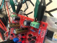
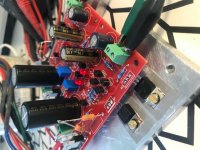
He, he, Jesper is back successful. You have Panasonic FM 330uF for C2 there I would say. C3 is rather far from M2 in your layout but you got lucky and the result looks to be stable. Check the rails with an oscilloscope also if you got one. How many uF is the tall and slim C1?
🙂
The C1 is 6800uF/35v Nichicon
My M2 is approx. 25mm. away from C3, i did check with a cheap oscilloscope i have, but i don't think this is good enough to tell the truth... the scopetrace is straight through 😛
I will try tomorrow to see if i can make some more accurate messurement's, forgot to meassure the "ac" on the output today.
Jesper.
Any scope is good enough to show you if an AC oscillation waveform of enough mV at many hundred kHz or few MHZ is riding on the DC line. You just put the short coil ground tip on the probe, you stick the probe like a two teeth fork in the Vout connector, then you choose AC couple for the scope at high sensitivity Vertical knob setting and you sweep the Horizontal knob.
P.S. Some DMM need time to settle for an AC reading on a DC output. So wait for final reading if you will see it changing number down and down with time. They could be just measuring their loose non shielded test leads picked up noise though. An oscilloscope probe with short ground attachment is more reliable because well shielded and with tight loop area.
P.S. Some DMM need time to settle for an AC reading on a DC output. So wait for final reading if you will see it changing number down and down with time. They could be just measuring their loose non shielded test leads picked up noise though. An oscilloscope probe with short ground attachment is more reliable because well shielded and with tight loop area.
Any scope is good enough to show you if an AC oscillation waveform of enough mV at many hundred kHz or few MHZ is riding on the DC line. You just put the short coil ground tip on the probe, you stick the probe like a two teeth fork in the Vout connector, then you choose AC couple for the scope at high sensitivity Vertical knob setting and you sweep the Horizontal knob.
P.S. Some DMM need time to settle for an AC reading on a DC output. So wait for final reading if you will see it changing number down and down with time. They could be just measuring their loose non shielded test leads picked up noise though. An oscilloscope probe with short ground attachment is more reliable because well shielded and with tight loop area.
So finally i managed to do some meassurements.
1. picture is AC
2. picture is DC
I have this cheap DSO068 scope, which i bought in lack of a real one.
I must say, that using the pc-scope program they offer for it, it's a little usefull, but i still don't trust it through. Anyway the trace on the DC picture looks like DC ;-)
Also i tried with one of my DMM's meassuring ac, and there is next to nothing.
Rgds; Jesper
Attachments
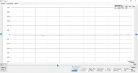
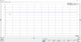
Its surely stable then. Congrats. Those tiny square artifacts must be sampling glitches in the software while the PC runs tasks. There are no real world squares in such measurements.
Its surely stable then. Congrats. Those tiny square artifacts must be sampling glitches in the software while the PC runs tasks. There are no real world squares in such measurements.
Yep, the square ones are computer"noise" 🙂...
But i am looking at a "real" used scope. Found some here in DK, but i donno if they are goos enough. Let's say a https://www.amazon.com/Rigol-DS1102E-Digital-Oscilloscopes-Bandwidth/dp/B0039N9ZBA
Is it worth something, or nogo? (Hmm. bad Jesper, offtopic sry...)
Rgds; Jesper.
If it was only the AC screenshot of 10mV resolution I would imagine that the root cause are tiny peaks in the random noise floor that it simply can't catch up with and it produces such shapes, but in the 5VDC resolution picture has some square dents which are super unlikely to be based on that noise given the 500 times less sensitivity.
I had that Rigol in the past. It was good and reliable machine. The one that put Rigol on the map. Although I had to replace its loud fan with a quiet bigger one.
Nowadays you would want something with larger screen and smoothing. Like this one: Siglent SDS1052DL+ 50MHz oscilloscope
I had that Rigol in the past. It was good and reliable machine. The one that put Rigol on the map. Although I had to replace its loud fan with a quiet bigger one.
Nowadays you would want something with larger screen and smoothing. Like this one: Siglent SDS1052DL+ 50MHz oscilloscope
Not as it is, circa 5V down limit is its stated spec, so yours works as intended. If you want to try the possibility of shorting one LED, replacing M2 with a Logic Level MOSFET like the MTP3055VL along with changing R9 to 2.2k, it may work well enough down to 3.1V limit or not but I did not originally intend it or check it in that way. There will be no negative mirror lower voltage version if made so.
Hi Salas,
Dimdim pointed out this particular comment so I just wanted to check with you. Are there any other changes I should be aware when lowering positive reg voltage to 3.3V? Suggestions for R1 value?
I wanted to use positive UBiB board to power ISO 3.3V to Soekris dam1021. I have few boards left from DCB3 build, thought I'd use them.
Going to use UBiB for powering dam with +/- 12V as well.
No other tentative changes to can go 3.3V. R1 calculation for CC current remains the same. Those suggestions have not been built before. So no guarantee, but likely to be OK.
Thanks Salas !
Do you have a link to post # for the formula? Having hard time searching this amount of pages 🙂 Apparently dam 1021 would require 10 mA at 3.3V.
Sounds like it is a bad idea since it was never built before.. 🙂 BTW, Soren is saying that "isolators can actually run on 2.5V-5V". I believe there's no need for mod if I go with 5V?
R1 calculation for CC current remains the same.
Do you have a link to post # for the formula? Having hard time searching this amount of pages 🙂 Apparently dam 1021 would require 10 mA at 3.3V.
Those suggestions have not been built before. So no guarantee, but likely to be OK.
Sounds like it is a bad idea since it was never built before.. 🙂 BTW, Soren is saying that "isolators can actually run on 2.5V-5V". I believe there's no need for mod if I go with 5V?
The formula is on the schematic and in the pdf guide. CC=0.6V/R1. With some expected small Vbe tolerance in the semis.
Median is 0.58V/R1 from the various reported results in different builds. Of course R1(Ω)=0.58V/CC(A) when solving for R.
Whatever Soren says. When you wind the trimmer fully down it may actually result little below 5V out. Something like 4.7V in enough builds. Keep it at lowest possible for safety.
Apparently mouser does not have the PF5102 JFET at the moment, is there an easy replacement or should I try to get it through ebay?
Nevermind, found Tea post in GB 🙁 Will try to contact him
Tea-Bag said:Just a note to those who have bought these boards, specifically those who did not buy minikits.
It was recently discovered that the PF5102 was end of life - and the supply has been quickly diminishing from other online distributors.
To mitigate this, I have purchased a significant supply of these transistors in order to make sure that demand for the UBIB boards can be met with significant transistors for some time into the future. It is possible that Mouser will have significant stock at the end of the year, but there is no certainty of that.
People who have bought the boards, but have not yet sourced there components may want to look into that quickly before the boards arrive and are sent, it could be any day now.
In a different than usual manner, I will offer just the PF5102 part to people who have purchased the boards for a reasonable price, but not allow any purchasing beyond the amount of transistor holes you have available for the boards you have purchased. I would suggest you inquire with me soon on this as for the current GB I can send them along with your current purchase and you can save significantly on shipping.
D1-D4
MUR120 vs MSRF860G
Is it OK to use the MSRF860G that comes with the kit or is MUR120 a must?
I'm using a 50 VA 15 + 15 Avel toroidal power transformer from Twisted Pear Audio. My constant current will be 200mA.
I do plan to use the IRF9610 and IRF610 for M1.
MUR120 vs MSRF860G
Is it OK to use the MSRF860G that comes with the kit or is MUR120 a must?
I'm using a 50 VA 15 + 15 Avel toroidal power transformer from Twisted Pear Audio. My constant current will be 200mA.
I do plan to use the IRF9610 and IRF610 for M1.
- Home
- Amplifiers
- Power Supplies
- Salas SSLV1.3 UltraBiB shunt regulator