Oh noooo! I just finished my V1.2R, and now we have V1.3?! 🙁
Earlier in this thread, you compared it with V1.1. What about V1.2R compared with this, Salas?
Earlier in this thread, you compared it with V1.1. What about V1.2R compared with this, Salas?
No straight subjective comparison opportunity yet. 1.2R was a "speciality" reg, the 1.3 is much more doable for everyone. Technically the 1.3 is superior even over the 1.2R for spec numbers. In the parallel voltage section mainly, in the series current section it has simpler CCS.
Hey Salas,
Thanks for the new BiB! I needed a bipolar psu for my BA-3 pre build. So, this is arriving just in time!
Cheers,
Greg
Thanks for the new BiB! I needed a bipolar psu for my BA-3 pre build. So, this is arriving just in time!
Cheers,
Greg
By the way, the negative section's Q1 orientation footprint has been corrected and I have already sent the files to Tea.
A build guide will be added as soon as I will be getting some answers about the R9's final generally recommended value vs max phase margin possibly attained audibility/not from a couple of the beta testers team hopefully until/in this weekend.
A build guide will be added as soon as I will be getting some answers about the R9's final generally recommended value vs max phase margin possibly attained audibility/not from a couple of the beta testers team hopefully until/in this weekend.
Hey Salas,
Thanks for the new BiB! I needed a bipolar psu for my BA-3 pre build. So, this is arriving just in time!
Cheers,
Greg
 You are welcome
@Salas Thank you for sharing this design.
I have a few questions:
1. What is the efficiency of the supply? E.g. in a Soekris DAC use case (180mA @ 10V positive, 60mA @ 10V negative)?
2. Do the active components get very hot (for same use case)?
3. Is there a specific current range where the regulator is effective in removing noise?
4. I presume the 50V rating of the C1 input capacitor can be lowered in case of 2x12Vac input (e.g. to 25V)? I would like to keep the design low profile.
Last edited:
1. My cheapo mains power socket meter shows 7.6W for a 50VA 12-0-12 Vac toroidal and a positive/negative 200mA CCS UltarBiB 1.3 configuration. Should be about there when set for the Soekris situation too. Maybe about 8W. I have 235Vac mains right now.
2. No problem
3. Up to 100-150mA spare current the M2's current noise contribution is behaving reserved.
4. Sure. I only have 15.5Vdc on C1 right now with MUR120 diodes while using the mentioned toroidal and mains voltage (answer 1).
Also... Put 10k trimmer instead of 20k, if not interested to ever use the reg for a really high Vout, so to have more turns in your range of interest.

1. My cheapo mains power socket meter shows 7.6W for a 50VA 12-0-12 Vac toroidal and a positive/negative 200mA CCS UltarBiB 1.3 configuration. Should be about there when set for the Soekris situation too. Maybe about 8W. I have 235Vac mains right now.
2. No problem
3. Up to 100-150mA spare current the M2's current noise contribution is behaving reserved.
4. Sure. I only have 15.5Vdc on C1 right now with MUR 120s using the mentioned toroidal and mains voltage (answer 1).
Also... Put 10k trimmer instead of 20k, if not interested to ever use the reg for a really high Vout, so to have more turns in your range of interest.
Thanks for the super quick feedback. Efficiency is good enough, dissipation should not be a big issue indeed. I already planned to go for the 10k trimmer, indeed should be more stable over time and especially easier to configure. I look forward to try this design out on my DAC! 😛
Fedde
Lets try some numbers:
Say for typical R1 values you use 2.2R in the positive and 3.9R in the negative. The formula* is CCSmA=600/R1. Thus 600/2.2=272mA & 600/3.9=154mA.
You said the Soekris current load spec is 180mA for the positive & 60mA for the negative. Because spare current in the reg is CCS-load then 272-180=92mA & 154-60=94mA. Balanced spare current on both rails is achieved, both M2s will dissipate the same. Zo and other characteristics will also be given a chance to be nearer in both sections.
The drawn current total should be CCSpos+CCSneg=272+154=426mA i.e. a very near total to my 200+200=400mA 7.6W pulling as measured test build. Should indeed be around 8W when set for Soekris because of the +26mA total in the described setting than the measured example's.
*When looking for R1 numbers through a CCS setting target the formula can be turned into R1=600/CCSmA. Say you go for 150mA setting, then 600/150=4R so 3.9R is the nearest. Its the one I just used for setting the UltraBiB's negative section current limit in the Soekris example.
Haha, My 1.1 version is still in progress, and 1.3 has been released. I am slow diyer. @_@
Is it worth to build 1.3 instead of 1.1? Mainly use for Soekris +-5V R2R ladder supply and 19V NUC.
How the sonic performance compare 1.3 and 1.1?
Thank you.
Is it worth to build 1.3 instead of 1.1? Mainly use for Soekris +-5V R2R ladder supply and 19V NUC.
How the sonic performance compare 1.3 and 1.1?
Thank you.
See post #23Haha, My 1.1 version is still in progress, and 1.3 has been released. I am slow diyer. @_@
Is it worth to build 1.3 instead of 1.1? Mainly use for Soekris +-5V R2R ladder supply and 19V NUC.
How the sonic performance compare 1.3 and 1.1?
Thank you.
Definitely, yes! At least my ears say so 😉Is it worth to build 1.3 instead of 1.1?
Hi Salas, All, Can you please help me to understand the working of this circuit.
(NAturally not the base is questionable, I know how a shunt reg works.)
But in this I do not udnerstand the Q2, Q3, J2 LEDs, and resitor parts. I know that the base role should be some kind of voltage reference, but don't get the point.
I remember in v1.2 a FET based fix current source simply feeded a resistor, and there a fix voltage could be counted, but here I simply don't get the point.
Q2 base is -0.6V from the top. Q3 base is -1.2 from top (on the 2 pcs 270 ohm the same current flows).
if Vout increasing the current on R5, R6, onVR1, and LEDs is increaseing . Q3 base will increase paralel with Vout (-1.2V).
Than Q3 will open more Q3 collector will "go" closer to Vout and Q4 close, and M2 close to, so Vout will decrease. That's fine.
But how does it give a fix Vout?
I don't understand
Thanks for the help in advance.
Szabolcs
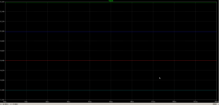
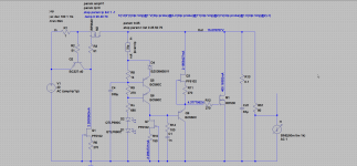
In one of my previous comments I stressed that this schematic has very poor thermal stability and this is normal since the voltage regulation relies to only a single p-n junction (which we all know is heavily temperature dependant). I did a simulation with stepped temperature 0, 25, 50, 75 deg. of the regulation transistor (Q5 on my schematic). On the first picture you can see the thermal drift of the output voltage - from 15.5V at 0 deg. to 13.8V at 75 deg. It's a quiet big difference, isn't it?
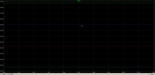
If a Zener diode is attached in the emitter of Q5, as shown on the picture 2, the things get better (picture 3) - from 15.08V at 0 deg. to 14.85V at 75 deg.
If a Zener diode is attached in the emitter of Q5, as shown on the picture 2, the things get better (picture 3) - from 15.08V at 0 deg. to 14.85V at 75 deg.
Attachments
Definitely, yes! At least my ears say so 😉
So you finished your experiment and put it on apps? Tell us more on where and how you liked it.
This zener will limit significantly the use of the regulator.
In practice it drifts -1 to -1.5% from cold to fully heated up after 30 mins. If it is set at 10.1V cold it ends up at 10V hot. If set when hot it ends up there again. That's all.
So you finished your experiment and put it on apps?
Yes! However I use slightly modified version, which I showed in post #61. My V1.1 versions are with the same CCS, so I think the comparison is fair.
The V1.3 is definately a keeper over V1.1 so far. I tested it powering both sides of JLSounds XMOS USB to I2S transport in my DAC with AD1865. This means I tested V1.3 only for digital power and I expect even more improvement for analog power.
V1.3 has much better resolution to put it short. It brings improvement in the whole frequency spectrum. Soundstage is the same compared to V1.1, but V1.3 has more details without them being "in your face", which I consider an advantage in an audio system!
Last edited:
Yes I saw that, you used your parts in hand and put a BJTs ring of two in the CCS tail instead of a JFET. Why you upped the current in Q5,Q6,Q9? Extra PM? Pushes up their current noise, but not a night and day thing.
P.S. Do you have local decoupling at the CCS? If not, maybe that is why it got jumpy and you altered it. Or the different bias currents. Running the 2SKs at IDSS pushes the BJTs.
P.S. Do you have local decoupling at the CCS? If not, maybe that is why it got jumpy and you altered it. Or the different bias currents. Running the 2SKs at IDSS pushes the BJTs.
- Home
- Amplifiers
- Power Supplies
- Salas SSLV1.3 UltraBiB shunt regulator