Scandal in Paradise
I do like the nick name 🙂
r
...Or not, and would actually look neater. Then nickname the whole JFET input stage mod and trimmed boards with external PSUs thing "Scandal in Paradise"
I do like the nick name 🙂
r
Will we cause a short if we mount both MOSFETs directly to the same heatsink without the thermal pads?
Q3 on the postive rail gets super hot and smokes while the output voltage is mostly ok. it drifts but stays near 12. what is up with that?
1.5A for an op-amp board (?) sounds much excessive. Even when discrete and when there is a controller. What is its real mA consumption for the +/-15V rails, can you measure? You wouldn't want to set the CC way high with R1 for no reason because there will be much heat and possible stability problems.
About parts there's nothing too special to say. Nichicon KZ for C2 and Nichicon ES for C3 work well. You may use 10000uF for C1 if the consumption is really beyond 1A and demands high CC setting. Some Nichicon or Panasonic. Use good brand 50 ppm resistors, fast & soft TO-220 bridge diodes like MSRF860G or VS-HFA04TB60PBF, and don't forget to put the negative section's Q1 in reverse orientation than what the print shows on the green test board. Also choose 10k VR1 for more turns in the voltage area of interest if you don't plan any higher than 25V rail application.
Opamp Board use 1A power supply as Allo report, because it use 6 opamp class A. So I think we need more than 1A, 1.5A should be better. Do you think 1A should be ok for the Katana Opamp? Thanks for your advices.
Katana DAC
Amazon Drive
Last edited:
There was one noise test done by a forum member about the noise comparision with a 12V zener with LEDs and when measured the 12V zener had the lowest noise than the string of LEDs. I agree the fact that other voltage level zeners have much higher noise than the LEDs but I believe 12V zener is the best in noise compared to LED string ( atleast in Bib 1.1 )? Whats your opinion salas?Needs two LEDS drop to keep the Q3's base above its collector level when at bottom range Vout. Non temperature compensated Zeners are substantial pink noise gens.
Opamp Board use 1A power supply as Allo report, because it use 6 opamp class A. So I think we need more than 1A, 1.5A should be better. Do you think 1A should be ok for the Katana Opamp? Thanks for your advices.
Katana DAC
Amazon Drive
If it had so hungry op-amp circuitry it would have sinks on some of its parts. Maybe much hungrier than chips those Sparko circuits but not Ampere class. The DC/DC converter could be asking much more current from 5V to scale up and feed them but directly from +/- 15V it should be far less current. When in doubt measure the consumption on the rails of interest. Its easy.
There was one noise test done by a forum member about the noise comparision with a 12V zener with LEDs and when measured the 12V zener had the lowest noise than the string of LEDs. I agree the fact that other voltage level zeners have much higher noise than the LEDs but I believe 12V zener is the best in noise compared to LED string ( atleast in Bib 1.1 )? Whats your opinion salas?
Maybe it was a special TC compensated Zener. Read this old but good article: http://mirror.thelifeofkenneth.com/lib/electronics_archive/Noise_Behaviour_of_Zener_Diodes.pdf
Attachments

Will we cause a short if we mount both MOSFETs directly to the same heatsink without the thermal pads?
Their drains are already connected together in this circuit so mounting them with no insulation on a common sink would not automatically hurt them. Given it electrically contacts those two parts ONLY. Not sinking other non insulated parts, especially not non insulated MOSFETS from another rail, and touches nowhere conductive. Of course the sink will become live at output voltage potential. So the sink itself must be floating regarding to other potentials and most of all ground. Not a good practice for a substantial chunk of metal that needs to be supported by the grounded chassis. Even accidentally touching a live sink with a wire or a probe can cause a bad situation. Better insulate the MOSFETS to it.
Q3 on the postive rail gets super hot and smokes while the output voltage is mostly ok. it drifts but stays near 12. what is up with that?
Q3 is the cascode BJT there so it sees the most voltage. Thus if there is much bias current (due to a shorted J2?) it will be the one to heat up much more than Q2. Normal bias current for all the TO-92s in this circuit is roughly 2mA. You may check by using Ohm's law on the voltage drops across associated resistors. R7 mV will indicate the bias current for J2 Q2 Q3.
*The Vref may still has proper current by Q2's Vbe/R5, since its an external branch, but a smoking hot Q3 is bad.
Maybe it was a special TC compensated Zener. Read this old but good article: http://mirror.thelifeofkenneth.com/lib/electronics_archive/Noise_Behaviour_of_Zener_Diodes.pdf
I found this on the forum about a member has posted about the Noise measurements he has made with both zeners and LEDs. Especially if you look at 12V Zener that has lower noise than an LED
Noise measurements for LEDs and zener diodes
--------------------------------------------
(C) Christer at DiyAudio.com
You are allowed to copy and use this information for your
personal and non-commercial use.
DESCRIPTION OF TEST RIG
-----------------------
The test rig uses three current sources of approx. 1, 5 and 20 mA
built using low-noise BJTs (BC559) to feed the device under test
(DUT) alternatingly. The noise was measured using two op amps in
in non-inverting configuration cascaded, both having a gain of 34,
making a gain of 1156 in total. The first op amp is a very-low-noise
model (LT1115) and uses a gain resistor of only 10 Ohms in the feedback
network. The gain resistor is thus 330 Ohms which works since the op
amp is only expected to output very low-level signals. The second op
amp is a low-noise type (NE5534) with gain and feedback resistors of
100 Ohms and 3.3 kOhms. The output was measured using a PC soundcard
(Creative Audigy LS in 16-bit 44.1 kHz mode). Each measurement consists
of a 10 second capture of the soundcard input and the RMS value for
this 10 s. signal was computed. The program was calibrated (using a
sine wave and an oscilloscope) to give aprroximately correct voltage
readings and all measurements were divided by 1156 to give the equivalent
input RMS noise at the first op amp, ie. at the DUT. No extra filters
except what is on the soundcard were used.
TEST METHOD
-----------
A spectrum of LED types ranging from IR to blue and of approximately
the same type were measured. All LEDS were selected to have an max
If of at least 20 mA, since this current was used in the test. Further
four 0.5W types of zener diodes were tested, two of them (5.6 and 6.8 V)
were deliberately selected close to each other but such that the 5.6 V
diode should be expected to have true zener breakdown and the 6.8 V one
to have avalanche breakdown. The other two were selected to be far away
from this "transition region". Two 1.3W zeners were also tested to see
how the power rating affects noise figures.
For each type of DUT, two devices (denoted #1 and #2 and presumably
from the same batch) were tested at the three test currents 1, 5 and
20 mA and the equivalent noise at the DUT was measured and calculated
as described above. For each combination of device and current, five
10-second measurements were made.
For reference, the voltage drop at each test current
was also measured for one device of each type.
MEASUREMENTS
------------
All values are RMS values
Idle noise:
----------------------------------------------------
Measured idle noise of amplifier with grounded input:
0.19 0.19 0.19 0.19 0.18 uV
(The theoretical max value was calculated to 0.16 uV for
20kHz bandwidth and 0.22 uB for 40 kHz bandwidth).
Measured idle noise of amplifier with 100 Ohm source resistor:
0.26 0.25 0.24 0.26 0.26 uV
(The theoretical max value was calculated to 0.20 uV for
20kHz bandwidth and 0.28 uB for 40 kHz bandwidth).
LEDs:
----------------------------------------------------
(All LEDs of brand Everlight)
IR204/P1 (IR):
#1 @ 1mA: 3.7 3.7 3.7 3.7 3.7 uV
#1 @ 5mA: 0.67 0.66 0.65 0.66 0.66 uV
#1 @ 20mA: 0.24 0.23 0.24 0.23 0.23 uV
#2 @ 1mA: 3.8 3.8 3.7 3.7 3.7 uV (Vf = 1.05 V)
#2 @ 5mA: 0.65 0.64 0.64 0.64 0.64 uV (Vf = 1.11 V)
#2 @ 20mA: 0.24 0.25 0.23 0.24 0.22 uV (Vf = 1.17 V)
EL202HD (red):
#1 @ 1mA: 0.31 0.32 0.31 0.31 0.32 uV
#1 @ 5mA: 0.26 0.26 0.27 0.27 0.27 uV
#1 @ 20mA: 0.39 0.36 0.37 0.36 0.37 uV
#2 @ 1mA: 0.39 0.37 0.38 0.38 0.35 uV (Vf = 1.82 V)
#2 @ 5mA: 0.32 0.30 0.30 0.30 0.31 uV (Vf = 1.89 V)
#2 @ 20mA: 0.41 0.40 0.41 0.41 0.46 uV (Vf = 2.09 V)
EL204ID (red-orange):
#1 @ 1mA: 0.31 0.30 0.31 0.31 0.31 uV
#1 @ 5mA: 0.25 0.26 0.26 0.26 0.24 uV
#1 @ 20mA: 0.41 0.41 0.48 0.40 0.41 uV
#2 @ 1mA: 0.35 0.31 0.29 0.30 0.32 uV (Vf = 1.64 V)
#2 @ 5mA: 0.25 0.26 0.27 0.26 0.30 uV (Vf = 1.74 V)
#2 @ 20mA: 0.40 0.40 0.39 0.40 0.41 uV (Vf = 1.90 V)
EL204YD (yellow):
#1 @ 1mA: 0.42 0.30 0.29 0.29 0.28 uV
#1 @ 5mA: 0.28 0.26 0.25 0.33 0.27 uV
#1 @ 20mA: 0.42 0.39 0.39 0.40 0.40 uV
#2 @ 1mA: 0.31 0.30 0.31 0.30 0.31 uV (Vf = 1.78 V)
#2 @ 5mA: 0.28 0.47 0.28 0.26 0.25 uV (Vf = 1.87 V)
#2 @ 20mA: 0.34 0.34 0.35 0.34 0.34 uV (Vf = 2.02 V)
EL204GD (green):
#1 @ 1mA: 0.68 0.50 0.50 0.47 0.46 uV
#1 @ 5mA: 0.35 0.30 0.28 0.28 0.29 uV
#1 @ 20mA: 0.36 0.35 0.35 0.35 0.35 uV
#2 @ 1mA: 0.46 0.46 0.44 0.44 0.41 uV (Vf = 1.82 V)
#2 @ 5mA: 0.36 0.33 0.32 0.33 0.32 uV (Vf = 1.92 V)
#2 @ 20mA: 0.39 0.40 0.39 0.41 0.40 uV (Vf = 2.12 V)
EL204UBD (blue):
#1 @ 1mA: 4.6 4.5 4.6 4.5 4.6 uV
#1 @ 5mA: 3.2 3.2 3.2 3.2 3.2 uV
#1 @ 20mA: 2.8 2.8 2.7 2.7 2.7 uV
#2 @ 1mA: 4.4 4.4 4.3 4.2 4.3 uV (Vf = 3.26 V)
#2 @ 5mA: 3.1 3.2 3.2 3.1 3.2 uV (Vf = 3.44 V)
#2 @ 20mA: 2.9 2.8 2.8 2.8 2.7 uV (Vf = 3.69 V)
Zeners:
---------------------------------------------------------
(All zeners of brand Temic.)
BZX55/C2V7 (0.5W 2.7V):
#1 @ 1mA: 1.1 1.1 1.1 1.1 1.1 uV
#1 @ 5mA: 1.0 0.88 0.85 0.86 0.87 uV
#1 @ 20mA: 1.0 0.81 0.72 0.72 1.1 uV
#2 @ 1mA: 1.2 1.1 1.1 1.1 1.1 uV (Vr = 2.03 V)
#2 @ 5mA: 0.91 0.88 0.87 0.86 0.85 uV (Vr = 2.50 V)
#2 @ 20mA: 1.1 0.80 0.77 0.73 0.71 uV (Vr = 3.02 V)
BZX55/C5V6 (0.5W 5.6V):
#1 @ 1mA: 5.3 5.3 5.3 5.3 5.3 uV
#1 @ 5mA: 2.9 2.9 2.9 2.9 2.9 uV
#1 @ 20mA: 1.7 1.6 1.6 1.6 1.6 uV
#2 @ 1mA: 5.3 5.3 5.3 5.3 5.3 uV (Vr = 5.68 V)
#2 @ 5mA: 2.9 2.9 2.9 2.9 2.9 uV (Vr = 5.77 V)
#2 @ 20mA: 1.8 1.6 1.6 1.6 1.6 uV (Vr = 5.81 V)
BZX55/C6V8 (0.5W 6.8V):
#1 @ 1mA: 16 16 16 16 16 uV
#1 @ 5mA: 21 21 21 21 21 uV
#1 @ 20mA: 5.8 5.5 5.5 5.5 5.6 uV
#2 @ 1mA: 25 25 25 25 25 uV (Vr = 6.93 V)
#2 @ 5mA: 13 13 13 13 13 uV (Vr = 6.96 V)
#2 @ 20mA: 4.6 4.7 4.5 4.5 4.4 uV (Vr = 7.00 V)
(Rechecked both devices due to their inconsistent
behaviour for 1 and 5mA).
BZX55/C12 (0.5W 12V):
#1 @ 1mA: 0.35 0.37 0.37 0.39 0.39 uV
#1 @ 5mA: 0.30 0.28 0.28 0.28 0.30 uV
#1 @ 20mA: 0.24 0.25 0.25 0.26 0.25 uV
#2 @ 1mA: 0.32 0.33 0.32 0.33 0.32 uV (Vr = 11.32 V)
#2 @ 5mA: 0.26 0.26 0.27 0.32 0.26 uV (Vr = 11.37 V)
#2 @ 20mA: 0.25 0.26 0.28 0.24 0.30 uV (vr = 11.42 V)
BZX85/C2V7 (1.3W 2.7V):
#1 @ 1mA: 0.77 0.77 0.77 0.77 0.76 uV
#1 @ 5mA: 0.62 0.61 0.63 0.61 0.60 uV
#1 @ 20mA: 0.55 0.55 0.54 0.55 0.55 uV
#2 @ 1mA: 0.78 0.78 0.78 0.78 0.78 uV (Vr = 1.30 V)
#2 @ 5mA: 0.62 0.62 0.61 0.62 0.62 uV (Vr = 1.61 V)
#2 @ 20mA: 0.57 0.56 0.57 0.56 0.56 uV (Vr = 1.92 V)
BZX85/C12 (1.3W 12V):
#1 @ 1mA: 0.49 0.53 0.48 0.50 0.52 uV
#1 @ 5mA: 0.54 0.55 0.58 0.46 0.48 uV
#1 @ 20mA: 0.44 0.35 0.38 0.36 0.33 uV
#2 @ 1mA: 0.42 0.43 0.46 0.48 0.41 uV (Vr = 9.84 V)
#2 @ 5mA: 0.40 0.35 0.35 0.37 0.29 uV (Vr = 9.89 V)
#2 @ 20mA: 0.34 0.33 0.31 0.30 0.31 uV (Vr = 9.94 V)
-----------------
#1 @ 1mA:
#1 @ 5mA:
#1 @ 20mA:
#2 @ 1mA:
#2 @ 5mA:
#2 @ 20mA:
Opamp Board use 1A power supply as Allo report, because it use 6 opamp class A. So I think we need more than 1A, 1.5A should be better. Do you think 1A should be ok for the Katana Opamp? Thanks for your advices.
Katana DAC
Amazon Drive
Like Salas said, that can't be right. +/-15V at 1A would mean 30W of power in a PCB area the size of an RPi. Without considerable heat sinking the board would literally melt after a few minutes of use.
I found this on the forum about a member has posted about the Noise measurements he has made with both zeners and LEDs. Especially if you look at 12V Zener that has lower noise than an LED
My experiences with high gain zero PSRR phono stages and PSUs is that their signal output FFT grass was bumping up a lot when I tried a Zener as unity gain Vref instead of LEDs or resistor (@ >20V rails). Anyways, you could try alternatives in the PSU for yourself. By the way, member Gerhard's very careful wide bandwidth FFT noise tests should be also considered.
Attachments
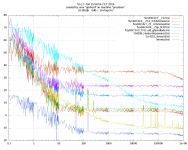
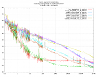
My experiences with high gain zero PSRR phono stages and PSUs is that their signal output FFT grass was bumping up a lot when I tried a Zener as unity gain Vref instead of LEDs or resistor (@ >20V rails). Anyways, you could try alternatives in the PSU for yourself. By the way, member Gerhard's very careful wide bandwidth FFT noise tests should be also considered.
Hi salas,
I agree the fact about other zeners. Consider if you are using 12V zener as per the measurements above and also the string of Red LEDs which are about 5 in numbers in series so which one will give more noise?
No, I used >20V voltage Zeners in those phono PSUs tests as I wrote. If that BZX85-C12 is so great an exception of an avalanche mode Zener I should get a few and try in some sensitive application on first chance. There can be more than one in series for higher Vz after all.
Probably a noob question :/
I'm considering this power supply to feed the Soekris dam1921 (or1941), it need +-5v for analog and +5v for digital.
As the boards are sold with 3 regulator , I was wondering if It Would make an improvement if I'm using a different regulator to to feed the +5V digital and +5V analog input.
Thanks in advance.
Those three sections on the pcb are completely independent for AC feeds, ground planes, and DC outputs. So isolation wise it does not make a difference using a completely different type regulator between digital and analog or the handy third section Ubib+ as already provided. To use rails of separate origin for analog and digital is of course always a good practice.
Would a toroid with 3 secondary windings be sufficient, or are 2 separate transformers needed to separate the rails correctly ?
One toroid with three separate wire pairs, one pair for each reg's AC input, will offer sufficient separation. One transformer for the analog +/- sections and another one for the digital+ section will bring even better separation but not a night and day difference.

- Home
- Amplifiers
- Power Supplies
- Salas SSLV1.3 UltraBiB shunt regulator