Is it recommend or beneficial to include any type of RF filtering on the mains input into my chassis before the power transformers primary? I have seen .01uF safety caps in use from both sides of the line input to ground used.
What is the allowable temperature range of the TO-220 devices on my heat sinks? My CC should be around 120mA.
What is the allowable temperature range of the TO-220 devices on my heat sinks? My CC should be around 120mA.
There is RC low pass filtering done by the Rf resistor and C1 capacitor down the road. So you could avoid extra measures in the mains input if not particularly contaminated with noise.
The TO-220 devices build up external temperature you can measure on their cases and internal higher one, the junction temperature, which matters most. That one has 150C meltdown spec for M1 and 175C for M2.
In practice because we want safe to handle builds and to increase their lifespan, up to 65C sinks temperature should be a logical max. Up to 50C is nicer of course. It will be somewhat higher on the TO-220 cases. There is thermal resistance from junction to case to sink.
Noise from the mains passes through primary to secondary due to transformer parasitic capacitance. How susceptible depends on type and construction. That's EMI riding the power grid line.
Quasimodo C//RC snubber tunes out the ringing created due to the transformer's secondary interaction with the bridge diodes. Another form of EMI. There are Cx Cs Rs places on the Ubib's pcb right after its AC input connector for optional snubber use. Rf C1 down the road in Ubib puts some attenuation action against all kinds of EMI reaching there. But some can still couple to leads and copper lanes.
Quasimodo C//RC snubber tunes out the ringing created due to the transformer's secondary interaction with the bridge diodes. Another form of EMI. There are Cx Cs Rs places on the Ubib's pcb right after its AC input connector for optional snubber use. Rf C1 down the road in Ubib puts some attenuation action against all kinds of EMI reaching there. But some can still couple to leads and copper lanes.
I am designing the snubbers for my Salas SSLV 1.3 regulator boards.
I am using a Quasimodo V3 surface mount board.
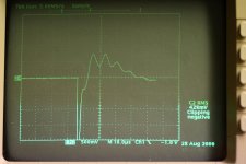
I have attached a photo of the scope trace I am getting after what seems to be the best achievable damping.
My final Cx=.0033uF Cs=.01uF Rs=75 Ohm
If I raise Cs much above .01uF I get repeated ringing across the scope that cannot be damped. With the .01uF Cs I only see this one event of positive ringing and there are no repeated rings on the scope trace. If I increase CS The amplitude of the ringing is repeated many times and also much greater amplitude. At the recommended initial .15uF CS the ringing cannot be damped at all.
With a Cs of .01uF the Cs/Cx ratio is 1:1. Thus I lowered Cx to .0033uF which give an approximate Cs/Cx ration of 3:1. This also lowered the peak voltage of the displayed initial one cycle ring by a few tenths of a volt.
Does my final result look reasonable?
Is the Cx of .0033uF likely high enough to overcome the capacitance of my transformer secondary winding(Unknown) and the 4 MSRF860 diodes in the PS bridge?
Is a 3:1 ratio Cs/Cx reasonable for proper in circuit operation of the snubber?
I am using a Quasimodo V3 surface mount board.
I have attached a photo of the scope trace I am getting after what seems to be the best achievable damping.
My final Cx=.0033uF Cs=.01uF Rs=75 Ohm
If I raise Cs much above .01uF I get repeated ringing across the scope that cannot be damped. With the .01uF Cs I only see this one event of positive ringing and there are no repeated rings on the scope trace. If I increase CS The amplitude of the ringing is repeated many times and also much greater amplitude. At the recommended initial .15uF CS the ringing cannot be damped at all.
With a Cs of .01uF the Cs/Cx ratio is 1:1. Thus I lowered Cx to .0033uF which give an approximate Cs/Cx ration of 3:1. This also lowered the peak voltage of the displayed initial one cycle ring by a few tenths of a volt.
Does my final result look reasonable?
Is the Cx of .0033uF likely high enough to overcome the capacitance of my transformer secondary winding(Unknown) and the 4 MSRF860 diodes in the PS bridge?
Is a 3:1 ratio Cs/Cx reasonable for proper in circuit operation of the snubber?
Attachments
I did post there. Have not received a response as of yet.
Post 1895.
Simple, no-math transformer snubber using Quasimodo test-jig
Post 1895.
Simple, no-math transformer snubber using Quasimodo test-jig
- Home
- Amplifiers
- Power Supplies
- Salas SSLV1.3 UltraBiB shunt regulator