Are you happy with your TT and cart? Do they rival your digital yet?An externally hosted image should be here but it was not working when we last tested it.
.
Jury's still out on that. I like the TT but I'm thinking of upgrading to a higher end cartridge. I have a HOMC SAE 1000E right now. Sounds great but maybe not better than my DAC.

Move to MC models at about 0.5mV output with boron cantilever and line contact stylus if you got 58-60dB gain ability for clearing well ahead your now cart class. Just my 2C.
Do you power the phono stage(s) by sharing the DCB1 reg BTW? I only see an SMPS for the pot motor.
My latest output for my new 22K amps...
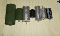
10uF K75-10 PIOs bypassed with 0.1uF FT-3s for a really deep rolloff.

Those 10uF PIOs are HUGE!!!!!!!!!!!!!!!!!!!!
10cm in length and ~5cm in diameter.

To be honest I felt that these things were too much, and I was pretty much ready to put back the ~5uF set.
I wasn't expecting such a big improvement. Even with 0 breaking in time, the bass is at least as low and articulate, the mids are way clearer (probably because of 1 main cap instead of two 2.2uFs I was using the past few days) and the highs are really through the roof. Still not on-par with the solo FT-3, but impressively decent for a freshly soldered set.
There is only some thinnish feeling on the mid-lows like last time, but I expect it to go away in a couple of days of listening.
I was expecting the 4.7uFs to arrive first so that I made my testing sequence more logical, but to be honest at this point I really do not think I will bother changing the coupling caps again.
I really need a new chassis for it though...
10uF K75-10 PIOs bypassed with 0.1uF FT-3s for a really deep rolloff.
Those 10uF PIOs are HUGE!!!!!!!!!!!!!!!!!!!!
10cm in length and ~5cm in diameter.
To be honest I felt that these things were too much, and I was pretty much ready to put back the ~5uF set.
I wasn't expecting such a big improvement. Even with 0 breaking in time, the bass is at least as low and articulate, the mids are way clearer (probably because of 1 main cap instead of two 2.2uFs I was using the past few days) and the highs are really through the roof. Still not on-par with the solo FT-3, but impressively decent for a freshly soldered set.
There is only some thinnish feeling on the mid-lows like last time, but I expect it to go away in a couple of days of listening.
I was expecting the 4.7uFs to arrive first so that I made my testing sequence more logical, but to be honest at this point I really do not think I will bother changing the coupling caps again.
I really need a new chassis for it though...
Attachments
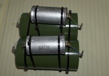
Less capacitors in parallel is always a good thing. Really big in 10uF though, need to be mechanically secured.
Are you talking about just for the measurement?
Sure I can try something like 2mm solid copper from power cable.
This one is solid 32awg silver plated copper
Sure I can try something like 2mm solid copper from power cable.
This one is solid 32awg silver plated copper
I did a quick test with some 1mm solid copper wire. No difference in DF. I will have to check tomorrow for sonics.
Do you mind explaining a bit what should I expect? Both sonically and electrically?
Do you mind explaining a bit what should I expect? Both sonically and electrically?
Trying to minimize extra resistance in the connections, maybe it could manifest a change in far higher test frequencies. Anyway don't bias for expecting something, just listen again.
Actually the outer connection was made on the FT3 leads and the PIOs are connected with the bridge. You think there might be a benefit moving the connection to the PIOs with bigger bridges to the FT3?
The above measurement BTW was a fast one with leads just caught with the probes and not cleansed or soldered.
The DF for properly cleansed and soldered caps is ~0.0040
The above measurement BTW was a fast one with leads just caught with the probes and not cleansed or soldered.
The DF for properly cleansed and soldered caps is ~0.0040
instead, connect the "through route" to the component that benefits most from the least inductance of the connection.Connect the leads to the outside world at the main capacitor.
The "return" route must also be arranged for least inductance.
This is something I offered up for discussion and testing many months ago.
I seem to recall only one Member reporting having tested the idea.
- Home
- Source & Line
- Analog Line Level
- Salas hotrodded blue DCB1 build