The first mosfet appears to drop from rail to 10 volts..... the next steady at 10 volts.
So, as long as your pre-regulated voltage ensures that Vsd is within the operating limits of the first mosfet then the regulator should work. Assuming the heatsinks can dissipate the power due to the voltage dropped by the first mosfet.
So, as long as your pre-regulated voltage ensures that Vsd is within the operating limits of the first mosfet then the regulator should work. Assuming the heatsinks can dissipate the power due to the voltage dropped by the first mosfet.
Yes. Its the more VDS you allow for the input MOSFET the less Ciss it will show (leveling out at a point) but dissipation goes through the roof meantime when in hot-rod.
Hmmm I will have to take a look at the data sheets. May have to change the caps in the pre regulator.
This will also be limited by the K170 I suppose?
This will also be limited by the K170 I suppose?
Last edited:
For the K170 and the LEDs headroom to ground with 20V raw across the PCB smoothing caps you have enough, plus mains drop margin. To kill the K170 it takes over 46VDC across those caps which would guarantee furnace dissipation on the input MOSFET with the mA current level you work now long before you went so high in voltage.
Hmmm I will have to take a look at the data sheets.
Look for this chart. 10V is good enough for that concern also.
Attachments
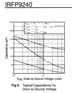
Excellent! Thank you! Clearly 10 is preferable to 7. In my haphazard testing, I thought there was more grip in the bass with better ambient cues at a higher Vds
With 25 volt caps, the supply is already on the edge with 18 vac transformer. The caps need to be upgraded to 35 volts. Looks like I was already running them too hard! I will get some caps with a higher rating first. This will take some time, but will report back asap.
Any suggestions that will fit the board? Thanks!
Any suggestions that will fit the board? Thanks!
The preregulator voltage with the bigger transformer is 26.5 V. Too high for the 25 volt caps. With the smaller transformer, the preregulated voltage is 21.5 V. The most convenient approach is to get a bigger transformer to fit into the existing case.
Last edited:
Guys I need your help with changing my output cap value because of my new amps.
The new monoblocks have 22k input impedance. Would a 4.7uF be ok or should I go for a 10uF just to be sure?
For type, it will probably be either K75-10 or K40 bypassed with an FT-3
Thanks
The new monoblocks have 22k input impedance. Would a 4.7uF be ok or should I go for a 10uF just to be sure?
For type, it will probably be either K75-10 or K40 bypassed with an FT-3
Thanks
I don t have any 10uF caps to go that high, but I will do some experimenting with parallel caps and see where it gets me. A 4.7uF will get me where I was with my previous amp.
At last I seal it with Shellac. I loudspeakers this is magic.
Nice!
I don t have any 10uF caps to go that high, but I will do some experimenting with parallel caps and see where it gets me. A 4.7uF will get me where I was with my previous amp.
200mS is 5Hz that you can do with 1.5uF on 22K. 2Hz is 500mS that you can do with 3.5uF.
I'm just about there with gathering all the bits to put my pre together.
All my music is digital sourced so I only need a USB input therefore I don't have an input selector. I may add one later if the need arises.
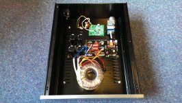
I've attached a picture of my proposed layout. The green board is an ODAC and in the future I may implement some kind of remote system once I get my head round how it works hence the motorized pot. Ive had a look at other layouts and they all vary so I was hoping someone would kindly sanity check my idea.
I have the board, pot and DAC at the rear to minimise signal runs and the tranny at the front. This way the MOSFETS are in the centre as I will be using the base as a sink. Ignore the outputs on the DAC - I put them there for testing.
Thanks in advance.
All my music is digital sourced so I only need a USB input therefore I don't have an input selector. I may add one later if the need arises.
I've attached a picture of my proposed layout. The green board is an ODAC and in the future I may implement some kind of remote system once I get my head round how it works hence the motorized pot. Ive had a look at other layouts and they all vary so I was hoping someone would kindly sanity check my idea.
I have the board, pot and DAC at the rear to minimise signal runs and the tranny at the front. This way the MOSFETS are in the centre as I will be using the base as a sink. Ignore the outputs on the DAC - I put them there for testing.
Thanks in advance.
Attachments
Using an oscope would help to make sure there will be no bleedthru of clock harmonics in the analogue stuff, better use different transfo for analogue and digital, and maximize boards distance or use right angles between them.
Thanks for the reply salas.
The ODAC is powered from the USB so the transformer is only powering the DCB1. I don't have an o'scope so I was hoping you may be able to give me blind guess and some guidance.
When/if I get the remote stuff sorted I will attemp to get another transformer in there.
The ODAC is powered from the USB so the transformer is only powering the DCB1. I don't have an o'scope so I was hoping you may be able to give me blind guess and some guidance.
When/if I get the remote stuff sorted I will attemp to get another transformer in there.
- Home
- Source & Line
- Analog Line Level
- Salas hotrodded blue DCB1 build