Thanks!
So the idea is that the voltage drop you expect over any resistor is Vf - Vgs.
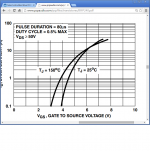
My 3 ohm resistor gives me about 500 mA. That means Vf - Vgs = 1.5.
The chart indicates that the Vgs will increase by about 1/2 a volt so, Vf - Vgs will be about 1. With a 1 ohm resistor, the current is 1A.
So the idea is that the voltage drop you expect over any resistor is Vf - Vgs.
My 3 ohm resistor gives me about 500 mA. That means Vf - Vgs = 1.5.
The chart indicates that the Vgs will increase by about 1/2 a volt so, Vf - Vgs will be about 1. With a 1 ohm resistor, the current is 1A.
Attachments
The chart indicates that the Vgs will increase by about 1/2 a volt so, Vf - Vgs will be about 1. With a 1 ohm resistor, the current is 1A.
Roughly, because there is no intermediate temperature curve shown and each sample will have a deviation. By experiment you will confirm the curve's deltaV for each polarity better.
Thanks Salas.
AndrewT,
I have the 1 Ohm, but not a second 3 Ohm. I will install the 1 Ohm and measure that. It should be fine, since the resistor with clip on heatsink has minimum 7 watts dissipation, so even 2 A will be fine in that regard.
AndrewT,
I have the 1 Ohm, but not a second 3 Ohm. I will install the 1 Ohm and measure that. It should be fine, since the resistor with clip on heatsink has minimum 7 watts dissipation, so even 2 A will be fine in that regard.
OK!
So, the voltage across the 1 ohm resistor is 1.3 and 1.4 volts. The heatsinks are at 45 degrees -- they were barely warm before. That is about 20 degrees above ambient. Now, they are like a low bias class A amp.
It was swapped from cement to Caddock, and changed from 3 to 1 ohm, so I cannot say that the improvement came from the hotrodding alone. But subjectively, there is more clarity and grip.
All tweaks now complete!
Heatsinks at 49 degrees C. Turned off the unit and quickly applied a thermistor to the diodes. 59 deg C. They are rated to 175 deg C. Seems ok by me, but will make better tests. Also, will measure temp of the transformer -- tomorrow.
It is a terrific unit! I just LOVE it. Thank you Salas for sharing this!

Thank you!
I taped a thermistor to the potted transformer that is inside a non-ventillated case that gets read via DMM. The transformer temp went to 49 deg C after about 1.5 hours of time spent on. The manufacturer says they designed the transformer for a 40 deg C above ambient temp rise. This was only 26 deg C -- well within the design parameters.
Should this somehow be vented? Even if just with a few holes, it would probably help. Or am I too fussy?
Yes, I just did that. I made a few, not many, but there is improvement immediately. I was concerned as the transformer temperature was around 53 degrees C. It should help a lot.
Of course, it sounds better with the holes! 😱 😛😉
😛😉
Of course, it sounds better with the holes! 😱
😛😉A 26 C degree rise for the outside surface is not bad.
But what are the internal temperature rises?
That's the bit that we as users cannot measure.
The manufacturers data specifies the use and the maximum ambient that THEY can guarantee the transformer.
But what are the internal temperature rises?
That's the bit that we as users cannot measure.
The manufacturers data specifies the use and the maximum ambient that THEY can guarantee the transformer.
With the holes, the transformer temp stabilizes at 27 degrees above ambient.
Given the new temperature of the sinks, there is no point to increase the voltage drop across the CCS.
It would make for an interesting comparison though:
Is hot-rodding with higher current "better" than hot-rodding with higher voltage?
Given the new temperature of the sinks, there is no point to increase the voltage drop across the CCS.
It would make for an interesting comparison though:
Is hot-rodding with higher current "better" than hot-rodding with higher voltage?
I started at 300mA, then wound up to 1A. I thought I heard an improvement then I tried 600mA and that sounded even better.
With the holes, the transformer temp stabilizes at 27 degrees above ambient.
Given the new temperature of the sinks, there is no point to increase the voltage drop across the CCS.
It would make for an interesting comparison though:
Is hot-rodding with higher current "better" than hot-rodding with higher voltage?
What you run now? 1.3A-1.4A? At what Vin-Vout?
Yes, 1.3 to 1.4 A, but I have not measured Vin at the increased load.
@500ma Vin = 21 V, Vout = 10. I will measure at some point, probably on the weekend.
It is interesting that some preferred lower level hotrods... I wonder why?
@500ma Vin = 21 V, Vout = 10. I will measure at some point, probably on the weekend.
It is interesting that some preferred lower level hotrods... I wonder why?
Last edited:
You never know each one's system synergy. Trust your own findings in your own system. If you have been there and you are in a better place now then its alright. If there are some recommended levels that you haven't tasted its easy to down gear and see for yourself.
I agree.
Whenever you change a component, and something changes in the sound, there are at least three choices:
1) The change in sound is brought in with the component
2) The sound was always present in the system... the new component revealed it.
3) A bit of both 1 and 2....
It makes for a crazy hobby. Same with the DCB1
I cannot understand why a circuit that uses so little power to begin with would sound any different when the shunt current is increased!
Better linearity and lower output impedance for the regulating mosfets
Oh and I think phase gets a bit better too
Oh and I think phase gets a bit better too
Last edited:
- Home
- Source & Line
- Analog Line Level
- Salas hotrodded blue DCB1 build