
Very near voltages on +/- rails, still not above 18V not to jeopardize the servo opamp. But maybe we can moderate them. How many mV drop between legs R1,R2 on each? mV/33R will answer mA. Lets see if we can drive the Leds to lower Vf total by upping those current limiting resistors. What value RxJ RyJ you installed by the way?
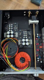
If talking about the pictured location, those are RyJ & RxJ. 5mV/1Ω=5mA. Right on design target. It seems that the Bargraph Leds are happier for Vf in your batch. Nearing 18V output. Still below max rails spec. R1 & R2 33R limit J1 & J2 IDSS to 5mA and feeds it to the Leds. If you replace all four R1 R2 with 68R you lessen ma and Vf for all the output voltages to back off a little. The R1 R2 locations can be seen in post#2 first picture for the dual mono PSU sections and polarities.It is 1R each, with drop of 5mv across both
Thanks. Ordered 68r.
The other board is set at 17.57 / 17.56 but as I understand I should replace all 4 R33.
The other board is set at 17.57 / 17.56 but as I understand I should replace all 4 R33.
I thought the boards were outputting about the same. Don't replace the 2x33R on the other channel yet. Do the higher one first and if it will drop in the 17.5V-17.6V range it will be a nice set with the other.

If you don't mind I ll be asking almost step by step questions shortly, as the work involves mains.
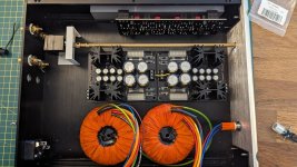
What is the best method to wire transformers, ac inlet and on off switch?
AC to a switch, then to transformers?
What is the best method to wire transformers, ac inlet and on off switch?
AC to a switch, then to transformers?


AC to switch to primary fuse to transformers. In this way its best because the fuse isn't live in case the switch is off but the chord is still plugged to the wall and you go replace the fuse. But integrated drawer fuse holder in IEC may force AC to primary fuse first switch to transformers then. Drawer type fuse holder is safer for not touching the fuse while engaged though. For two 50VA transformers on 240V UK mains use one T1.25A (slow blow) 250V fuse protecting both of them.If you don't mind I ll be asking almost step by step questions shortly, as the work involves mains.
What is the best method to wire transformers, ac inlet and on off switch?
AC to a switch, then to transformers?
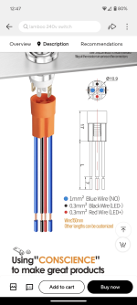
Advertises 250VAC/7A rating on those pictures, its likely because accepting wires capable enough for that.I have a switch in my cupboard. Any chance you can confirm it can take AC , I see it can be, asking just in case, thanks.
With respect to the primary circuit wiring, it would be good to consider what a Safety agency, such as UL, CSA or TUV would use as criteria if one’s project was submitted to them for evaluation. As a hobby builder, one tends to focus on “making it work”. Safety criteria is somewhat the opposite: what happens when it breaks? The effect of any component failing (shorted or open) is evaluated. Again, as a hobby builder, we want to think “that won’t happen” but a Safety agency will test what happens when it does.
The case in point is the primary fuse sizing. The fuse must be sufficient in size and delay characteristic to handle the inrush surge when power is applied but also small enough that it opens in case of a fault. In this case the “fault” to be considered is a short of a transformer secondary, or of the rectifiers or filter capacitors. The primary fuse must open to “stop the fire” that would otherwise result if such a fault were to occur and power remained applied.
Most hobby builders will be loath to apply a short to the power circuits of their equipment. The effects can be quit startling: sparks, loud bangs, and yes: fire! But really you should, particularly if you think you might fall asleep with the equipment left on.
The primary fuse size & type I recommend is also listed on some power solutions companies fusing charts for 100VA single phase 230-240V AC transformer so it should be adequate.
Thanks, Salas. I forgot to order shoulder washers for transistors and will get fuses, and thicker gauge wires for hook-up. Fingers crossed will be able to connect everything soon.
On another note, I have been trying to understand how the 2511 pot works as I will be using it for this build. Connected it in between cheap stereo speaker output and its speaker and I get the volume to appear only at the last nudge of a turn (say the last 20 degrees of 300 available) and it goes almost straight to a full. What am I doing wrong?
On another note, I have been trying to understand how the 2511 pot works as I will be using it for this build. Connected it in between cheap stereo speaker output and its speaker and I get the volume to appear only at the last nudge of a turn (say the last 20 degrees of 300 available) and it goes almost straight to a full. What am I doing wrong?
Attachments
- Home
- Source & Line
- Analog Line Level
- Salas DCG3 preamp (line & headphone)