A big thank you to Salas and Tea-Bag! Also zdr for the LDR attenuator!
Great fun building this! 🙂
Excellent!
Can you post a pic of the backside of the two units connected together?
What BJT's did you use for the Q1 Q2 mirrors?
nash
Excellent!
Can you post a pic of the backside of the two units connected together?
What BJT's did you use for the Q1 Q2 mirrors?
nash
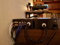
Attatched the backface. Nothing fancy, and I did not bother with a connector for the link between the chassis. I figured a direct connection would be best 🙂
The chassis makers in China had already put some holes in the backplate, so I had to make the best of it. Put a few there myself aswell.
-3x phono inputs plus a 3.5mm input.
-1x phono output, 1x line 3.5mm and 1x headphone 3.5mm
-1x Passive bypass output(Just volume and source selection).
-USB connector for the LDR input board.
Before I finish up the chassis with feet an knobs, my plan is to make some sort of markings on the backplate for input and outputs.
As for the Q1 and Q2 I used like stated in the BOM and kindly provided matched by Tea-Bag - BC560 🙂
Attachments
Do you have info on the LDR's output impedance as it is now set? This parameter can play an easy tonal tuning role if the total system will need some since its controlled by software.
I see modded pro TT and vinyl records... nice
I see modded pro TT and vinyl records... nice
The load impedance is set in the code for the Arduino controlling the LDR board. I had it defined to 330k, other than that it's out of my hands 😛
But I guess I could try to tweak this setting to se how the sound changes if needed 🙂
Attenuator impedance is set to 20k.
Turntable is a heavy modified SL-1210. It's a really great machine! 😉
But I guess I could try to tweak this setting to se how the sound changes if needed 🙂
Attenuator impedance is set to 20k.
Turntable is a heavy modified SL-1210. It's a really great machine! 😉
As for the Q1 and Q2 I used like stated in the BOM and kindly provided matched by Tea-Bag - BC560 🙂
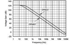
That's the technically more potent for peak OLG and easier to match standard. It won't change in the BOM because its the scientifically better choice. The BC327-40 alternative one is the lower 1/f self noise ~10dB milder but wider peak OLG plateau choice for the willing to find a good Hfe batch and wilder to match. It takes sockets to compare subjectively its impact in different systems and tastes. There is an early consensus its a subjective upgrade for tone and clarity. Although one member with the biggest speakers between other testers reported it indifferent for changes if not little bit boring for dynamics. In both cases there is 107dB OLG at 20kHz for the DCG3 though, no worries. An OPA627 offers just 60dB there to help you see the situation in some wider frame.
Attachments
The load impedance is set in the code for the Arduino controlling the LDR board. I had it defined to 330k, other than that it's out of my hands 😛
But I guess I could try to tweak this setting to se how the sound changes if needed 🙂
Attenuator impedance is set to 20k.
Turntable is a heavy modified SL-1210. It's a really great machine! 😉
Its probably 5k output impedance max if it works like a 20k input impedance series pot...
I have 2x SL-1200 MK2 stored away that may come handy at a point 🙂
All these values are configurable for the LDR within the Arduino code. Both input and output impedance invidually. I am not much of a code guy, so I wouldn't know what it actually does. 😛
There is a calibration process after adjusting these parameters wich does some sort of compensation. 🙂
Maybe a brighter mind will chime in.
There is a calibration process after adjusting these parameters wich does some sort of compensation. 🙂
Maybe a brighter mind will chime in.
Did you listen with your dcg3 on Klipsch Heresy III through double mono Aleph J yet?
I have! And I love it!
It's open sounding without ever beeing harsh and the soundstage is just excellent! Sure invites me to go above my normal listnening volume.😛
No hiss or hum too 🙂
Again, thank you so much for this great circuit!😉

Hi Salas,
My DCG3 is currently running (very happy with it) mounted on a piece of board. For the final housing, I think about outsourcing all milling and drilling. Any chance you could provide me with the exact coordinates of the DCSTB and DCG3 PCB mounting holes and other dimensions?
My DCG3 is currently running (very happy with it) mounted on a piece of board. For the final housing, I think about outsourcing all milling and drilling. Any chance you could provide me with the exact coordinates of the DCSTB and DCG3 PCB mounting holes and other dimensions?
Congrats. Some picture? For what system/use is it for?
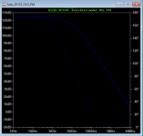
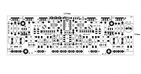
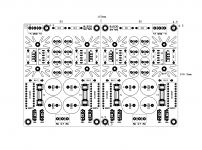
What I could make out about boards dimensions and their mounting points coordinates from grid view on the PC then with a ruler on my samples is attached. See if you can confirm on your boards too.
What I could make out about boards dimensions and their mounting points coordinates from grid view on the PC then with a ruler on my samples is attached. See if you can confirm on your boards too.
Attachments
Hi Salas,
Thanks for the info and the help. I cannot easily get the dimensions from my boards since they are already populated & termporarily mounted and seriously spoiling my ears... And I also thought it would be most logical and exact to get all dimensions straight from the PCB design files.
Thanks for the info and the help. I cannot easily get the dimensions from my boards since they are already populated & termporarily mounted and seriously spoiling my ears... And I also thought it would be most logical and exact to get all dimensions straight from the PCB design files.
I used the Eagle grid view and the cross hairs cursor. Then a ruler and calipers on the real PCBs. But its not a coordinates numerical answer from the program itself.
Thanks very much.
There are still so many design options to work out. Motorized pot or old school. Input selector or not, and if so, what type? I am not very fond of relais because in my builds they tend to degrade sound quality except when brand new. My favorite solution is a rotational switch from old HF equipment or measuring equipment. They have very good silver contacts and only get better over time. And if I use one of those, will it be remote controlled? And do I want a display or not? Or just a ring of LEDs around the volume knob, or maybe no external controls at all, just my remote? I wrote a little program running on an Arduino to read the IR stream from the very stylish apple remote.
Decisions decisions decisions.....
Tnx for the help and the excellent DCSTB and DCG3 designs and all the headaches this project is causing me :=)
You are welcome. No matter the final style of peripheral configuration you gonna decide, we will be happy to see and read about your work in progress.
Thanks very much.
There are still so many design options to work out. Motorized pot or old school. Input selector or not, and if so, what type? I am not very fond of relais because in my builds they tend to degrade sound quality except when brand new.
You mean for attenuation or source selection ?
I'm only familiar with pot, relay and ldr for attenuation and I've read a lot of people stated the opposite from your findings: switches usually degrade with the passage of time, especially the cheap open type, and quality of sound varies. I assume this is not the case with the expensive ones like Elmas and the like.
First I'd like to say this pre sounds great in front of my F5 turbo V3 monos, and I can plug in some headphones too! Thank you Salas for the design and Teabag for providing the boards/kits!
I'm using a Velman K8084 to provide tone controls, which is currently direct coupled to the DCG3. The volume control is on the front of the Velman. All the parts in the Velman have been upgraded to Dale CMF55s and Wima caps, except the input cap will be Audyn Plus. I've tried rolling a few opamps in it and only one so far (AD823) gives a near zero offset going into DCG3. I'm going to be trying some Burson V6 vivid discretes in there and their spec sheet states a 3mv offset is possible. I realize the servo may take care of it but I'd rather it not have to compensate for any more than itself so I want to insert another cap between the Velman and DCG3.
How do I calculate the value of the cap?
Nice to hear of yet another successful build. Post some pictures if you like. DCG3's direct input impedance is 333k. From there you can calculate any time constant with an input coupling capacitor. Being high it can allow small value good quality capacitors that in bigger values could be much more expensive. You could still compare the result with or without depending on the input offset burden you would allow and watch how the DCG3's servo can take it under control including transient states like accidental on/off of the Velleman tone control front end while the DCG3 and amps are on etc.
- Home
- Source & Line
- Analog Line Level
- Salas DCG3 preamp (line & headphone)