At last, I found some time to do the first electrical test! It came to life easy! I remind you that I' m using two DCG3 stereo modules, each one powered by one half DCSTB.
First DCG3: power rails @ 17,22V/-17,22V bias @ 111mA/113mA
Second DCG3: power rails @ 17,34V/-17,35V bias @ 113mA/113mA
Should I trim anything?
I haven't insert the opamps yet but DC offset was easily adjusted around 1mV although it fluctuates, of course.
My DMM has lost the ability to measure temperature but I can say DCG3 was just warm after 15 min and DCSTB even less with its 2,5" heatsinks.
OK! I need to put some work into the chassis before any listening. I hope to have news by the weekend🙂Looks like a perfect start, nothing to trim.
Thanks for your quick answer. Pardon my ignorance, but it says in your instructions: "R6 sets the gain. 1k for 3x, 499R for 2x, 1.5k for 4x." There must be something that I don't quite understand. What gain do I get if I change just the R6 from 1k to 470R?Yes no problem with R7 470R instead of 499R, it will just make 3.12x which is peanuts practical difference to 3.0x
For 2x spot on put both R6 and R7 470R
 Or is it a no go and I must change the R7 as well?
 Salas
Salas AlephJ Mimi! second channel up (Failure was faulty cable from source)!
Offtopic sry... 🙂
Jesper.
Did you also notice those large gunshot earmuff like phones the drummer wore in the Pidgeon clip? Those have Sony 7506 drivers inside. They are specials for high isolation called UltraPhones. Drummers must protect their hearing the most as the kit is loud and if it leaks in enough they pump up the volume of their foldback mix in the cans too. So they end up with ringing ears after longish sessions or when performing loud live events. In Ear monitors do that job well too.
Thats very interesting. You have good eyes to spot them!!
Jim
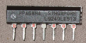
Unsure how the upa68HA should be turned..is it text side on upa68 towards text on pcb?
Refer to my post #908
nash
Slim uPA has the N logo indicating pin1 which goes to the white stripe side on PCB
Fat uPA has its upper left corner slant. Again indicating pin1
The board has pin identification printed on every uPA pad also
Ultimately as you watch from the connectors PCB edge towards correctly installed uPAs the left one shows its face the right one shows its rear
Fat uPA has its upper left corner slant. Again indicating pin1
The board has pin identification printed on every uPA pad also
Ultimately as you watch from the connectors PCB edge towards correctly installed uPAs the left one shows its face the right one shows its rear
Attachments
Salas, any issue using 49.9R for R4 gate instead of 33R? Its just that I have them but if 33R works better in your opinion, I'll add that to my order for parts.
Thanks. nash
Thanks. nash
Salas, any issue using 49.9R for R4 gate instead of 33R? Its just that I have them but if 33R works better in your opinion, I'll add that to my order for parts.
Thanks. nash
33R works slightly better and its recommended but 49.9R can work with no practical issue meanwhile
33R works slightly better and its recommended but 49.9R can work with no practical issue meanwhile
OK will stick with 33R. Thanks.
X,
Thanks for the detailed review.
http://www.diyaudio.com/forums/anal...g3-preamp-line-headphone-108.html#post4954414
Look forward to starting my build soon. 🙂
Thanks for the detailed review.
http://www.diyaudio.com/forums/anal...g3-preamp-line-headphone-108.html#post4954414
Look forward to starting my build soon. 🙂
If anyone's interested I removed the RyJ resistor and used a trim-pot on one end of a cable with the other end soldered to the RyJ location on the PCB.
To raise the V- voltage by 0.4v required a 91 ohm resistor.
Salas, really like the preamp - thanks for sharing it with us!
To raise the V- voltage by 0.4v required a 91 ohm resistor.
Salas, really like the preamp - thanks for sharing it with us!
I've hooked up just one DCSTB into the DCG3 and everything looks OK (no smoke!).
The voltage on the single DCSTB I'm using is around 17.2v -/+ with no load so looking good.
However I may have a problem with the other DCSTB though as I connected my trannies to this to check it and the + & - voltages were about 0.4v different with no load. V+ is +17.39v while V- is -16.98v.
I checked components - they all look OK - any thoughts on what I can do or check?
Thanks
Add some value to the weak line's RyJ to come up. Its just mainly due to Leds tolerances.
More PS Questions.
Salas, I have a some more PS questions.🙂
1) Will the Rx and Ry resistors only raise the output voltage if you substitute values larger than 1 ohm?
If so, how high can it be raised?
2) Assuming I'm trying to get around 12V output...would I short out 3 LEDs, which theoretically should give me about 12.25V?
3) Does it matter which LEDs I short?
4) Next, would I just increase the value of the 33 ohm resistors to lower the voltage .25V to 12V?
5) Can PF5102s with a Idss over 8mA be used? If not, why?
6) I don't understand what you stated earlier about the Schottky diodes changing the voltage by .7V.
I thought after AC is rectified, the voltage goes up by a factor of 1.4.
So 12VAC turns into 16.8VDC.
Thanks!
the peak of a sinewave is sqrt(2)*Vac...............
I thought after AC is rectified, the voltage goes up by a factor of 1.4.
So 12VAC turns into 16.8VDC............
So a pure sinewave of 12Vac has a peak of 16.97Vpk
But the mains is not pure sinewave and it is not constant.
A 12Vac transformer with a transformer regulation figure of 9% will have an output of 12Vac * {1+0.09} = 13.08Vac and that will have a peak of 18.5Vpk when the load is disconnected.
When the mains varies, the transformer input voltage varies.
If the mains is 6% low, then that last value is reduced to 17.45Vpk and when the mains is 6% high the peak becomes 19.6Vpk.
Note this range (17.4 to 19.6Vpk) is quite different from your first calculation showing 16.8Vdc.
If anyone's interested I removed the RyJ resistor and used a trim-pot on one end of a cable with the other end soldered to the RyJ location on the PCB.
To raise the V- voltage by 0.4v required a 91 ohm resistor.
Salas, really like the preamp - thanks for sharing it with us!
You mean you finished it and listening? Any pictures to share?
Trying a value with a trimmer is a hands on valid way of course but you can also predict about those resistors. Coming from the pdf guide:
"Measure in mV DMM scale across Rx or Ry. For 1R the readings directly translate to mA. Predict the new needed R value for covering a voltage difference by R=(Vdif/mA)*1000. Replace with that resistor the relative rail's Rx or Ry. Example: You found got 5mA current running through a rail's leds REF but you need add 0.2V to make it symmetric. R=0.2V/5mA=0.04*1000=40R."
*I remind that's mostly an aesthetic fix as this design will not perform any worse for offset due to some asymmetry in its rails values.
Salas, I have a some more PS questions.🙂
1) Will the Rx and Ry resistors only raise the output voltage if you substitute values larger than 1 ohm?
If so, how high can it be raised?
2) Assuming I'm trying to get around 12V output...would I short out 3 LEDs, which theoretically should give me about 12.25V?
3) Does it matter which LEDs I short?
4) Next, would I just increase the value of the 33 ohm resistors to lower the voltage .25V to 12V?
5) Can PF5102s with a Idss over 8mA be used? If not, why?
6) I don't understand what you stated earlier about the Schottky diodes changing the voltage by .7V.
I thought after AC is rectified, the voltage goes up by a factor of 1.4.
So 12VAC turns into 16.8VDC.
Thanks!
1) Yes they will only raise. How high to reach is free to your other project's spec and it can be calculated from the formula in my previous answer to Marcus1. Quoting further from the pdf guide:
"Those RxJ, RyJ positions are a place to also add much more voltage for using DCSTB in other projects with higher rails. For a lower rails project individual leds can be shorted out losing 1.75V with each. This PSU has been designed with DCG3 in mind but I knew that you would ask sooner or later 🙂"
2) Yes.
3) No. You can even short units in between lit ones, broken ladder fashion, to look nice.
4) Check the voltage results first because tolerances may be on your side sometimes and then try lower the reference current with >33R degeneration if needed.
5) They can but not homing in well for supplying DCG3 rail levels considering the other parts values listed. For general use of DCSTB you decide parts parameters and set it.
6) The Schottky diode voltage loss is about half a normal junction diode's loss. So you still calculate by rectification's 1.41x but your 2x diode loss to deduct in the end is smaller.
- Home
- Source & Line
- Analog Line Level
- Salas DCG3 preamp (line & headphone)