That's an awesome looking design. I love the look of the Luxman stuff. One of my friends is letting me borrow his L-509X. It sounds very good, and it's only one measley box!
Thanks, the 509x is a very nice and pretty amp, build quality is almost accuphase godtier level.
Regards,
John
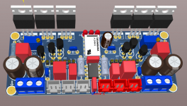
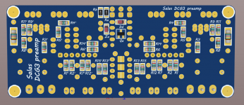
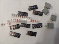
Hello, everyone. I finished the layout of the preamp. The first activation. Everything is OK, well, almost everything. I made a mistake in the payment.The channel 1 integrator did not work. That's why I built the layout. R10-10R. The offset current is 114mA. The sound, at first glance, is very good, you need to warm up. You can order the production of printed circuit boards UltraBiB and DCG3. Subsequently, I will replace the capacitors with Wima, miniMELF resistors. Tomorrow I will try to remove the RMAA spectra.
Attachments
Good health to all. Performed measurements with the RMAA program. The preamp is powered by both channels in parallel from a single UBiB. Everything is located on the table. Not the best interblock wires (long 1m). I measured the sound card on itself and measured the Preamp. What can you tell from the results? Am I doing the right thing? Maybe you need to set certain levels in RMAA? I hope that after replacing the resistors, the noise will be lower.
Attachments
Hello. Please tell me the number of the post where it is indicated how to correctly transfer the preamp to the balanced mode. I plan to provide for these changes on the printed circuit board. Thanks.
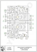
And one more question. There is an unbalanced signal source and a balanced power amplifier. I plan to use a converter. How will the sound path be organized correctly? Use two preamps in balanced mode and put the converter in front of it. Or one preamp, and turn on the converter after it, before the power amplifier?
And one more question. There is an unbalanced signal source and a balanced power amplifier. I plan to use a converter. How will the sound path be organized correctly? Use two preamps in balanced mode and put the converter in front of it. Or one preamp, and turn on the converter after it, before the power amplifier?
Attachments
Last edited:
@Crazoff - Take a look at the posts starting with 5323.
I'm planning to put the single-ended to balanced converter at the front end of my preamp (after the input selector, but before the stepped attenuator). This way, you can take advantage of the strong drive capability of the DCG3.
I'm planning to put the single-ended to balanced converter at the front end of my preamp (after the input selector, but before the stepped attenuator). This way, you can take advantage of the strong drive capability of the DCG3.
Salas ")
My DCG is still going strong at 4? - 5? years now
I am planning to buy a new galaxy chassis, like the one which holds my DimDim DAC and put my DCG in that box, giving me some more playground and space.
Because ::
I'am building an ESP32/Arduino Preamp. controller, Bluetooth (low energy/BLE), input selector, 7 segment retro display's and a motorized Alps potmeter, IEC out delayed and so on and so on etc... etc...
I have an idea to add a "mute" function also to the setup, but being in doubt howto implant that. - Info is that my source selector will be relay driven and both L & R will have 100Kohm resistors attached to GND nomatter if they are selected or not.
The potmeter attached to input will be Log. 50K x 2 Alps.
Output is now connected directly to phono's.
Nice posting here again BTW...
Jesper.
Hi... thank's Salas.
So instead of using the NEC as mute, would it be good to just switch off the lineout / headphone out after the 49.9R / RZJ 1W resistors giving me the possiblilty to cut off lineout & headphone out independtly.
Or is it a bad idea doing it this way Salas.
Jesper.
So instead of using the NEC as mute, would it be good to just switch off the lineout / headphone out after the 49.9R / RZJ 1W resistors giving me the possiblilty to cut off lineout & headphone out independtly.
Or is it a bad idea doing it this way Salas.
Jesper.
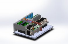
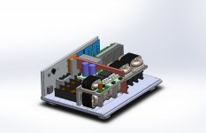
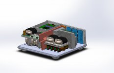
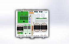
The pre amp casing is getting to be a big puzzle, it's full.
and i still need to add more, it's a challenge.
According to the cad, the weight will be 37 kilo's
we have:
7 UBIB's (4 for dcg3, 3 for dam1941)
2 sslv's (neurochrome)
2 tvicol zero's (5V for control, 12V for elma lin motor)
2 dcg3's
1 neurochrome buffer (processor out)
7 r-core transformers
2 silk tvc's with elma 24steps rotary switch
1 dam 1941
ian canada fifopi, reclockpi, stationpi, uc conditioner, conditionerpi and linearpi dual
etc etc
regards,
John
Attachments
Last edited:
You could do it that way also. To be independent. Don't switch them off to ground creating a signal output short. Have a three way switch selecting HP, Line out, Nothing. "Nothing" could be a 10k dummy load to ground not to pick noise.
Would it also be handy to short unused inputs to 10k, so they don't pickup noise? I think i have seen that before.
regards,
John
- Home
- Source & Line
- Analog Line Level
- Salas DCG3 preamp (line & headphone)