Agreed. I was just wondering whether two unmatched M1's having different gain characteristics could be less than optimal and so a match would be a good idea? I dont suppose matching M2 matters since it is acting as a cascode. Just trying to understand this better.
nash
I did not match M1s so I don't know if there could be something in it. I didn't expect anything interesting at this bias level low Gfs range for little differentiations.
I did not match M1s so I don't know if there could be something in it. I didn't expect anything interesting at this bias level low Gfs range for little differentiations.
Thanks Salas for your explanation.
nash
Very interesting project indeed, thanks a lot for bringing this to life! I'm already subscribed to the GB and I'm planning to build up a balanced pre with the boards.
To avoid the implementation of a quad-type volume pot for balanced use, the LDR3x board from Tortuga Audio came to my mind. Sorry for the maybe noob question - would the LDR3x suit the DCG3 as a replacement of the volume pot?
Best regards, Henning
To avoid the implementation of a quad-type volume pot for balanced use, the LDR3x board from Tortuga Audio came to my mind. Sorry for the maybe noob question - would the LDR3x suit the DCG3 as a replacement of the volume pot?
Best regards, Henning
I don't know how you are implementing your balanced vol pot, but in general you will find that a two track vol pot will not work in a balanced impedance line. That wipes out your quad vol pot for a stereo balanced line idea.Very interesting project indeed, thanks a lot for bringing this to life! I'm already subscribed to the GB and I'm planning to build up a balanced pre with the boards.
To avoid the implementation of a quad-type volume pot for balanced use, the LDR3x board from Tortuga Audio came to my mind. Sorry for the maybe noob question - would the LDR3x suit the DCG3 as a replacement of the volume pot?
Best regards, Henning
Look at B.Putzeys' balanced vol pot topology.
He imports the balanced line, converts to unbalanced, applies the adjustable attenuation/gain, converts back to balanced.
Hi.
Salas, I've got an unused sigma22 from an old and forgotten project. I suppose that it must work well with the DCG3.
Thanks!
Ignacio
Salas, I've got an unused sigma22 from an old and forgotten project. I suppose that it must work well with the DCG3.
Thanks!
Ignacio
It should cooperate alright I suppose too. Only ask them what D5 R10 it optimally takes in that reg for a +/-17V setting. 12V D5 and 24K R10 maybe.
Evening all here.
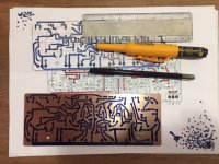
Eventhrough i could just wait for the very nice DCG-3 pcb's to be ready in the group buy, i could not resist trying to make my own amateur one's 😱
Well it aren't nearly done yet... but i sort of got started now...
This, if succes will be near the limit of what i can do by hand i think! So really exited how it would come out in the end?
Attached picture of raw pcb, top_layer.
Rgds; Jesper.
Attachments
Its a nice learning experience. Good luck. Only remember after pcb assembly to do checks with the DMM in continuity mode (beep!) so to verify all parts will have right circuit connections, no shorts to GND, etc. before finally attempting to power up.
Thanks Salas....
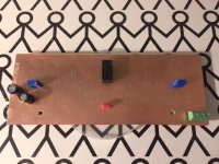
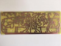
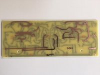
So finally i am done with pcb.
Sry... Salas, there was a typo on the pcb (jlp16) 😀 ... Otherwise all vent well drawing/etching it up.
Took around 7-8 hrs. including time for cutting and drilling all holes.
-Hey but i like it!
Next step is to "beep" it all out, after soldering the top/bottom layer spot's
Rgds; Jesper.
Attachments
Nice. If it will prove working alright try protect it from oxidization in the end somehow. Tinning or plastic film spray or something.
SK10 Flux from Kontakt Chemie is very useful, protective and solder friendly 😉
Does it have elements of long time protection too like Deoxit on contacts or is it mainly for helping in the short term during assembly?
Does it have elements of long time protection too like Deoxit on contacts or is it mainly for helping in the short term during assembly?
Allways was wundering about that too!
Anyway, when times come, and if i succes i will look into it...
I have a special small "glass" bruss, witch i allways use to clean tracks, when pcb's are done.
Jesper.
I found some info here https://www.soselectronic.com/artic...-soldering-easier-with-a-flux-sk10-spray-1506
flux - an efficient agent to improve solderability
wide possibilities of usage on a PCB and any other joints
also protects from corrosion
in a dry environment can be left on a PCB as a protective layer
filled by an environmentally friendly gas (CO2)
after usage it´s not necessary to clean a nozzle by spraying “upside down”
available in spray or in 1l/ 5l bulk
I found some info here https://www.soselectronic.com/artic...-soldering-easier-with-a-flux-sk10-spray-1506
flux - an efficient agent to improve solderability
wide possibilities of usage on a PCB and any other joints
also protects from corrosion
in a dry environment can be left on a PCB as a protective layer
filled by an environmentally friendly gas (CO2)
after usage it´s not necessary to clean a nozzle by spraying “upside down”
available in spray or in 1l/ 5l bulk
Yes... I have used that before!
But i allways clean track's with my "Glass" brush, and when all cleaned up, i sprayed with that spray, giving a real nice shiny surface 🙂
https://www.google.dk/search?q=glasb%C3%B8rste&client=ubuntu&hs=Kko&sa=X&channel=fs&biw=1366&bih=621&tbm=isch&imgil=yVaGLDAnmZjnxM%253A%253BXT8wsz1prBL99M%253Bhttp%25253A%25252F%25252Fwww.butik4281.dk%25252Fbutik%25252Findex.php%25253Fmain_page%2525253Dproduct_info%25252526products_id%2525253D133&source=iu&pf=m&fir=yVaGLDAnmZjnxM%253A%252CXT8wsz1prBL99M%252C_&usg=__GBfttRZ6PID5vQRo8r6uN-VAiHo%3D&ved=0ahUKEwilmNfOovvPAhUElxQKHcvzBDoQyjcILg&ei=QBkSWKX4M4SuUsvnk9AD#imgrc=yVaGLDAnmZjnxM%3A
Rgds; Jesper
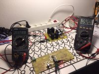
Evening here 🙂
So something is working.
I soldered in the relay circuit, and when giving the DCG3 pcb GND(0) and 17.23vdc, the leds, and the relay goes on after ~4 sec.
I tried to meassure the voltage on the coil, and when powering up, at the moment the relay engages there is, in a blink of an eye 25vdc, and then it goes down to ~9.20vdc.
My Ra resistor is 68K, Rb is 15K, Ca is 100uF, and red led's are 20mA/1.6v.
The relay is Omron G5V-2 330ohm coil, and the NEC from the BOM is ~1000ohm coil.
The resistance is 0 ohm between contacts when engaged, and the click sounds "right"...
Are there any considerations about the coil resistance/transistor etc...
Regards; Jesper.
Attachments
Long term (>5yrs) I don't know, mid term it works perfectly IMO.Does it have elements of long time protection too like Deoxit on contacts or is it mainly for helping in the short term during assembly?
But depends on what you're used to do: if you make your own pcb, you clean it and you populate it immediately, there are probably better products, but if, after cleaning, you plan to solder the components after a while (even a few days) the SK10 is the best I ever used.
Evening here 🙂
So something is working.
...
Are there any considerations about the coil resistance/transistor etc...
Regards; Jesper.
Why you use a 5V relay when the spec in the BOM is 12V relay? It will wear out at almost 100% more coil voltage than nominal. See if when replacing one LED with 560R (put it standing upright) will still work. (You may need lower voltage Zener).
Why you use a 5V relay when the spec in the BOM is 12V relay? It will wear out at almost 100% more coil voltage than nominal. See if when replacing one LED with 560R (put it standing upright) will still work.
Hi Salas.
The G5v-2 is the type... The coil is 12vdc...
No problem. I was just asking, about the transistor and the circuit, nothing Else.
I see That the 9,1v zener is proberly why voltage goes down 9.2vdc...
Just being curius here 😄
It looks like it pulls more current than the NEC though. So it probably drops much in the LEDS. Its no problem to trigger, the relays have a wide enough range below and above nominal.
Measure Leds Vdrop and feel heat on Leds relay and Qa. We don't want the Leds or Qa to burn out early in use.
P.S. Is this the one? http://eu.mouser.com/ProductDetail/Omron-Electronics/G5V-2-DC12/?qs=lK7M36XCk6JxdWY/V6sVqw==
If yes you put a 0.5W relay in place of a 0.14W relay. 42mA pull vs 12mA pull. Good luck Leds & Qa.
- Home
- Source & Line
- Analog Line Level
- Salas DCG3 preamp (line & headphone)