I actually power the op-amp from the left side and the relay from the right in my realization but this is only practical and not critical since its about few mA
Good Then 🙂
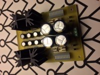
I startes soldering my "left" psu now, and i stumbled upon, that the pf5102's should be within the 6-8mA range.
At witch voltage should i test/match at? (17vdc???)
Rgds; Jesper
Attachments
At 6-8mA range bcs when with R1 & R2 33R to have predictably about 5mA through both sides Leds. Use 9V test because the drop across them will be around so in the PSU with 18V transformers.
At 6-8mA range bcs when with R1 & R2 33R to have predictably about 5mA through both sides Leds. Use 9V test because the drop across them will be around so in the PSU with 18V transformers.
Morning!
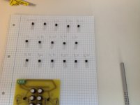
Salas can you confirm this is correct for testing IDSS at PF5102's ?
Jesper.
Attachments
Its alright (Jesper yes, correct)
Hi...
Just wanna tell, that if i had known better i would have bought more than 16pcs. of thoose critter's 🙂
I barely only got two pairs 😱 (PF5102)
Jesper.
Attachments
R1 & R2 can be manipulated to make almost all useful in case of need. Imagine Tea how many he has to measure reject and pick for those and J3s and M3s for everybody
A jFET has an Idss. that is the current that flows when the Vds equals the datasheet test voltage, the Vgs is zero (Gate connected to Source) and the device is cold (25°C).
The Id when in a circuit is usually different.
You can change the Id by changing the Vds, but this does not work well. See the curve in the datasheet.
A better way to change Id is to insert a resistor (Rs) in series with the Source lead.
The voltage developed across the Rs subtracts from the voltage applied across the gate to what was the Source end. The resistor effectively reduces Vgs applied to the jFET. You can now set the source current to any value less than Idss. In the extreme if you used a 10M resistor the Id would drop to a few nanoamps. The jFET is virtually off.
It's the added resistor Rs that allows you to set the jFET current to the value your circuit needs.
R1 & R2 can be manipulated to make almost all useful in case of need. Imagine Tea how many he has to measure reject and pick for those and J3s and M3s for everybody
A jFET has an Idss. that is the current that flows when the Vds equals the datasheet test voltage, the Vgs is zero (Gate connected to Source) and the device is cold (25°C).
The Id when in a circuit is usually different.
You can change the Id by changing the Vds, but this does not work well. See the curve in the datasheet.
A better way to change Id is to insert a resistor (Rs) in series with the Source lead.
The voltage developed across the Rs subtracts from the voltage applied across the gate to what was the Source end. The resistor effectively reduces Vgs applied to the jFET. You can now set the source current to any value less than Idss. In the extreme if you used a 10M resistor the Id would drop to a few nanoamps. The jFET is virtually off.
It's the added resistor Rs that allows you to set the jFET current to the value your circuit needs.
Thank's both of you... allway's good and usefull answers in this thread; even if quistions sometimes seems straiteasy 😉
Anyway...
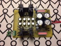
It's ALIVE (well left-psu it is)

So now it's my turn to stray with some calculations i think.
I forgot to buy the 1R resistors for the LED-banks, so i tag-soldered two R47 in series in instead.
My calculations is, that if voltage around 17.23VDC, and resistor is 94R then the current flow in LED's are 17.23/94=18.33mA each, or 183.3mA for one LED-block...
I did use 2.2K resistors at output for temporarely bleeders, as i also forgot to buy thoose 3.3K bleeders too

Output is 17.23 on both + and -, so everything seems to be in symmetry.
Now i would like to test the PSU, with full load, so i have to load the PSU with 7watt? But i am in doubt howto calculate those resistors, because there is both +17.23 and -17.23VDC rails..
Any hint's 😎?
Rgds; Jesper,
Attachments
Thank's both of you... allway's good and usefull answers in this thread; even if quistions sometimes seems straiteasy 😉
Anyway...
It's ALIVE (well left-psu it is)
So now it's my turn to stray with some calculations i think.
I forgot to buy the 1R resistors for the LED-banks, so i tag-soldered two R47 in series in instead.
My calculations is, that if voltage around 17.23VDC, and resistor is 94R then the current flow in LED's are 17.23/94=18.33mA each, or 183.3mA for one LED-block...
I did use 2.2K resistors at output for temporarely bleeders, as i also forgot to buy thoose 3.3K bleeders too
Output is 17.23 on both + and -, so everything seems to be in symmetry.
Now i would like to test the PSU, with full load, so i have to load the PSU with 7watt? But i am in doubt howto calculate those resistors, because there is both +17.23 and -17.23VDC rails..
Any hint's 😎?
Rgds; Jesper,
Your led bars look normally glowing in the photo. They should have around 5mA each. Measure mV across your R47s. They maybe are at about 2.35mV each. Your outputs matching is excellent for a non directly adjustable PSU. DCG3 would not care much about that but its good to see. 150R/5W resistors would be like DCG3 channel load if in the place of the bleeders.
I don't know whether you have to test the psu at full load (I never do), because that makes your dummy load unneccessarily big. Otherwise Ohm's law is your friend: when you want to test at 300mA load your dummy load need to be 57R-ish and be able to sink more than 5W, so a power resistor 50R 25W on a sheet of aluminum should do. And make that two each since you have two polarities to test. 😉
17.23/94=0.1833A, or 183.3 ma!!!!
Jim
No way. His Leds would be dead already. There is no full output across Rx & Ry. There is just their tiny drop from the Vref mA running through. Dictated by the PF JFETs and their 33R Rs. R47 means 0.47R so 0.94R for two in series. He has about 5mA through those.
Sorry for interrupting the discussion. I keep debating if I should use Salas' bib low voltage regulator for powering the preamp. I understand it is but more difficult to set it up so the question if I gain anything... There was only one report of improver clarity or soundstage which sounds worth it,but there was no a/b comparison.
Salas, Tea-Bag any tricks of setting up LV regulator apart from two wire configuration?
Salas, Tea-Bag any tricks of setting up LV regulator apart from two wire configuration?
Meaningful A/B is difficult for now because the builds are few and between three continents. My local friend's build who has a common BIB uses not the same pot value and type. He also has the PCB now but with K170 J1-J2s and OPA2134 beyond the PSUs differing. Tham wrote me he is also doing proto-board DCSTBs now. Being the one who has done mono V1.2Rs & double mono BIBs in the same build in his own system he will be in a position to tell differences in a more "controlled" manner. He is also good in that as I have seen his impressions were reliable through the course of his long beta testing.
Salas, Tea-Bag any tricks of setting up LV regulator apart from two wire configuration?
See post #79 for power requirements and CCS limits
No way. His Leds would be dead already. There is no full output across Rx & Ry. There is just their tiny drop from the Vref mA running through. Dictated by the PF JFETs and their 33R Rs. R47 means 0.47R so 0.94R for two in series. He has about 5mA through those.
Yes i see i forgot a zero before the 94 in my calc. Ofcause its 17.23/0.94 giving 18.3mA.
I will meassure the voltage around the RxJ//Y's tomorrow. I see my lights are a little more red, than on the other pictures of the psu.
Jesper
Even worse, it would mean 18.3 Ampere. Those RXJ-RYJ resistors are not sitting across Vout. Using 17.23V in a calculation with those is irrelevant. You can use that for the bleeders only.
Even worse, it would mean 18.3 Ampere. Those RXJ-RYJ resistors are not sitting across Vout. Using 17.23V in a calculation with those is irrelevant. You can use that for the bleeders only.
Doohh 🙂
I really have to learn to be better to explain in English.
What i was trying to calculate is the current flow, through each single LED inside LED-block (DC10EWA)
Datasheet tells me, MAX is 20mA each, giving 200mA for the hole package.
I just want to be sure, that the LED's are not overloaded ?
Also to figure out, why the LED color is red more than orange?
Goodmorning then; Jesper.
- Home
- Source & Line
- Analog Line Level
- Salas DCG3 preamp (line & headphone)