I populated all the parts on the board except the mosfets which I will do once I map the drill holes on the heat sinks.
Coming to the matched quad BC560, I have the following numbers mentioned by Tea-Bag in the kit.
1. 430 217 (hFE) presume its the hFE value
2. 430 222
3. 430 187
4. 430 181
So from the above list should I club 1+2 and 3+4?
I have no first hand experience on how Tea's mini-kits are parts coded because I just build immature version PCBs when researching prototypes with not yet finalized type or value parts that I sort out myself. But I would presume 430 is the Hfe and the other number some sorting method for his own tracking. Because a 560C can't have around 200 hfe. C type is much stronger hfe category. If indeed all have the same 430 hfe you have nothing to select. Having a DMM with hfe function? Use it to confirm they are very near to each other. Don't mind the absolute number though, testers differ. Don't touch them when to measure, they get affected, use a tool to handle them.
I have no first hand experience on how Tea's mini-kits are parts coded because I just build immature version PCBs when researching prototypes with not yet finalized type or value parts that I sort out myself. But I would presume 430 is the Hfe and the other number some sorting method for his own tracking. Because a 560C can't have around 200 hfe. C type its much stronger hfe category. If indeed all the same 430 hfe you have nothing to select. Having a DMM with hfe function? Use it to confirm they are very near to each other. Don't mind the absolute number though, testers differ. Don't touch them when to measure, they get affected, use a tool to handle them.
Yes. We index the parts and then sort them on the spreadsheet. So 430 is hfe value as measured with my multimeter setup for hfe.
Yes. We index the parts and then sort them on the spreadsheet. So 430 is hfe value as measured with my multimeter setup for hfe.
Thanks Tea-Bag & Salas, now I should be able to complete the board tonight and just wait for the new RCORE next week to test out the board 🙂
Stronger ib current dedicated testers usually show higher hfe than DMMs. So we only care the numbers match well on same test gear despite how absolutely high may appear between different test gear. But why we would want high enough hfe in this? Because the Q1,Q2 current mirror is a CCS drain load for the uPA JFETs. Higher hfe=higher current gain transistors that lead to higher mirror load impedance. Thus to higher open loop gain in the preamp. In other circuitry like symmetrical NPN-PNP BJT input MC phono preamps only matching is important and almost any hfe level will do. JFET input like ours has high impedance and no input DC offset simply by its nature.
Finished the board with all the components except the mosftes.
An externally hosted image should be here but it was not working when we last tested it.
An externally hosted image should be here but it was not working when we last tested it.
An externally hosted image should be here but it was not working when we last tested it.
I see that you sat the trimmers with their set screws as located on the board graphics after all 🙂
No solder has gone through. You have a light hand. I usually solder with thick enough wire until it pops to the upper pad
Then I go touch up on the upper pad if not well filled. Not to all places, some I forget to inspect they are done 😀
Double strong mechanically but its admittedly also harder to clean or rework. I have a desoldering gun station at least 🙄
I got mine working for a while, but putting it on the chassis took more time. I used my homemade CNC (not too reliable) but good enough to cut aluminum, drill holes and cut the vents. The last thing I have to do is clean it up by sand paper and get anodized.
I encountered some grounding issues on mine when I first powered up. I can hear the humming noise when I increased the volume on the pot but when it reached the max volume, the noise goes away. Did try to isolate the problem using star grounding and also followed the attached schematic but same thing. I get tired of it trying many things, so I decided to connect audio ground directly to chassis ground. The DCG3 became dead quite. Some said, its not a good idea but hey! it worked, so why not?
I used my DCG3 as a preamp for my audio system and also a headphone amp using Senheiser 600. Can't complain, sounds good so far. Only disadvantage, I can't carry around to listen with my headphone. 😀
I tried the software, out of your head, it sounds amazing on surround sound movies as if your listening to 7.1 channel. I didn't buy it yet since its a bit pricey but I might consider in the future.
Well, thanks Salas for sharing DCG3 with DIY community. This would definitely be a keeper.


I encountered some grounding issues on mine when I first powered up. I can hear the humming noise when I increased the volume on the pot but when it reached the max volume, the noise goes away. Did try to isolate the problem using star grounding and also followed the attached schematic but same thing. I get tired of it trying many things, so I decided to connect audio ground directly to chassis ground. The DCG3 became dead quite.
Some said, its not a good idea but hey! it worked, so why not?I used my DCG3 as a preamp for my audio system and also a headphone amp using Senheiser 600. Can't complain, sounds good so far. Only disadvantage, I can't carry around to listen with my headphone. 😀
I tried the software, out of your head, it sounds amazing on surround sound movies as if your listening to 7.1 channel. I didn't buy it yet since its a bit pricey but I might consider in the future.
Well, thanks Salas for sharing DCG3 with DIY community. This would definitely be a keeper.
I see that you sat the trimmers with their set screws as located on the board graphics after all 🙂
No solder has gone through. You have a light hand. I usually solder with thick enough wire until it pops to the upper pad
Then I go touch up on the upper pad if not well filled. Not to all places, some I forget to inspect they are done 😀
Double strong mechanically but its admittedly also harder to clean or rework. I have a desoldering gun station at least 🙄
Yes Salas, I usually sometimes or most of the times do light solder and if all works fine then resolder the light pins 🙂
Just scared of oversoldering or heating up the pads too much and if some part has to be replaced then desoldering is a pain with my small desoldering gun. I will take into all your suggestions once I power it up and check that everything is working fine.
Yes I just followed the pin marking on the PCB which is what I follow to the "T" 😀 and after you said like the trimmer orientation does not matter on this board I thought lets go with the markings as thats what makes the build.
@ fredlock
I like your homegrown CNC box result. Also has nice dimensions for housing this preamp. What are they?
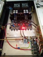
Regarding your solution for chassis referencing to silence my guess is it has to do with the signal passing through the switch relay board which is powered from an independent transformer in your implementation so its local PSU does not see the rest of DCG3's PSUs grounding. Your pot sits on the same board. My switch board steals DC from the DCSTB and there was no hum but I habitually reference my audio ground return straight to the mains grid earthed chassis regardless. Brings the circuit's return to same potential as the box. So no interference fields can develop between them. As pointed with red arrows in my attachment. I add that fail safe mains earth lift scheme if and when there's a system hum problem. So no worries, well done. Please show it to us again when anodized, its nice to see how it ends up, and let us know how it further goes for sound after you will have even more play with it.
By the way is that "Out Of Your Head" software result reminding a headphones dummy head recording effect like this? Virtual Barber Shop
I like your homegrown CNC box result. Also has nice dimensions for housing this preamp. What are they?
Regarding your solution for chassis referencing to silence my guess is it has to do with the signal passing through the switch relay board which is powered from an independent transformer in your implementation so its local PSU does not see the rest of DCG3's PSUs grounding. Your pot sits on the same board. My switch board steals DC from the DCSTB and there was no hum but I habitually reference my audio ground return straight to the mains grid earthed chassis regardless. Brings the circuit's return to same potential as the box. So no interference fields can develop between them. As pointed with red arrows in my attachment. I add that fail safe mains earth lift scheme if and when there's a system hum problem. So no worries, well done. Please show it to us again when anodized, its nice to see how it ends up, and let us know how it further goes for sound after you will have even more play with it.
By the way is that "Out Of Your Head" software result reminding a headphones dummy head recording effect like this? Virtual Barber Shop
Attachments
@ manniraj
No need to over-solder it when finalized. Its very sturdy as it is. Don't follow me and my crazy iron. It will be accident prone to solder touch a populated board's top side.
No need to over-solder it when finalized. Its very sturdy as it is. Don't follow me and my crazy iron. It will be accident prone to solder touch a populated board's top side.
I am planning to use a LDR based Arduino controlled volume control board - Arduino LDR. Will be sourcing this from one of my friends and use the Salas source selector board and take the output from that to this LDR and it will be calibrated for 20k impedance. Hopefully it should work well and above all the convenience of remote control for the volume purpose albeit not for the source selection.
If I use an R-core 2x15V transformer the benefit will be reduced heat for the MJE15030/31 regulators as less voltage needs to be dissipated compared to 2x 18V.
Will the lesser tension on these devices degrade the performance in anyway ?
Or the closer I can get to 18-19 Volt DC after the rectifier the better ??
Will the lesser tension on these devices degrade the performance in anyway ?
Or the closer I can get to 18-19 Volt DC after the rectifier the better ??
With small voltage drop across the DCSTB, beyond putting it closer to drop out at possible weak public electricity hours, the transistors will show more internal parasitic capacitance. 5V in-out=Vce or more across those pass transistors allows them to work and sound better. In other words have no less than 22V after the rectifier if you can.
Because of my mistake of placing the order wrongly I got an EI core transformer. The EI transformer uses CRGO cores so hopefully I think it should be fine to use for dcg3 as replacement by the vendor is not possible and if I have to then need to order again 🙄
Its a line preamp not a thousand times gain MC phono preamp so it won't be in dire need of the lowest field emitting transformer type the industry has to offer. EI has good split between primary and secondary. Just put it at the other end of the box behind the DCSTB or BiB away from RCAs and signal wires, also have its mains and output leads well dressed and short. I used smallish standard production split bobbin frame transformers in mine that tend to warm up because made in plastic casing and nothing too bad happened. Yours is probably already better.
Yes Salas, the trafo is very well built and quite heavy and I already use the similar kind for my 834p phonostage clone with 120V secondary voltages and its dead silent.
If you see my existing preamp cabinet layout I have a nice 2mm thick partition plate for the trafo and BiB psu's separated neatly from the amp boards. I am going to replace the BA3 with the DCG3 in that position and might use the Musical Fidelity X10-D tube buffer as is in the same position with a toggle switch with buffer or without 🙂
If you see my existing preamp cabinet layout I have a nice 2mm thick partition plate for the trafo and BiB psu's separated neatly from the amp boards. I am going to replace the BA3 with the DCG3 in that position and might use the Musical Fidelity X10-D tube buffer as is in the same position with a toggle switch with buffer or without 🙂
An externally hosted image should be here but it was not working when we last tested it.
Last edited:
Salas, what kind of distortions (meaning magnitude) do I need to look out in case of using BIBs with DCG3 ?
With Tek465 and 10X probes I can't pick anything
I went with normal 4 wire output with BIBs, 3-5cm long.
The new preamp plays very good from the word go. Just that, is amazing.
With Tek465 and 10X probes I can't pick anything
I went with normal 4 wire output with BIBs, 3-5cm long.
The new preamp plays very good from the word go. Just that, is amazing.
Last edited:
With so short Kelvin connections and double BiBs its very normal not to pick anything odd on the rails. I had picked 1MHz 150mV pk pk oscillation in a matrix board dcg3 beta proto that did not have c6,c7 using a mono BiB on much longer shared output cables. Looked like a rounded peaks elongated triangular. That one I solved with two wire output mode.
- Home
- Source & Line
- Analog Line Level
- Salas DCG3 preamp (line & headphone)