5% good 2% excellent 1% brilliant 0% divineI remeasured all with that precaution way and got bit higher values in steady room temperature. What % of matching is considered to be sufficient? I have high Hfe once with values equal to 425/420/418/407. All the rest is in the range of 340-360. I’m looking for the set to upgrade my second unit with LDR volume control.
So what do mere mortals like myself do?
I dont have a curve tester but have several MM's with Hfe function. Just pick the pairs with the highest Hfe?
Thinking of buying 100 of these, since I need 8 for my balanced build. Will that suffice or should I buy 200? Is this the best choice at Mouser?
BC32740BU ON Semiconductor / Fairchild | Mouser
Thanks.
nash
Just make 5% or better pairs from those with the higher Hfe among 100-200pcs. Use one same DMM for testing them all. Preferably in one same day session. They also list an MCC brand 327-40 that claims fT 260MHz which is strange. The Philips standard is 100MHz and the Fairchild follows it. A strange fruit that MCC type from California and maybe interesting if its not simply due to different lab testing datasheet parameters.
Forgot to mention the 0.5% demigod level matching though 😀
What proper diyer could go higher then this?😉
So what do mere mortals like myself do?
I dont have a curve tester but have several MM's with Hfe function. Just pick the pairs with the highest Hfe?
Thinking of buying 100 of these, since I need 8 for my balanced build. Will that suffice or should I buy 200? Is this the best choice at Mouser?
BC32740BU ON Semiconductor / Fairchild | Mouser
Thanks.
nash
Group buy -> Curve testing, sorting -> Personal delivery 😀
The BC560C is easy to get in high Hfe and match. And it plays fine. The BC327-40 lower noise type is for the aficionados who want to go the extra mile in tonal exploration. And someone might don't like it in the end. So its an option and because its difficult in consistency it takes buying and sorting out many. Not lending itself to centrally pre-select.
Hmm - didnt think it would make a difference. Have to try someday.
BTW: Have some 2SB716 laying around. Could maybe match and test? Are supposed to be good. Have plans using them in an amp.
BTW: Have some 2SB716 laying around. Could maybe match and test? Are supposed to be good. Have plans using them in an amp.
BTW: Have some 2SB716 laying around. Could maybe match and test? Are supposed to be good. Have plans using them in an amp.
Those Hitachi are very good Japanese transistors alike the Toshiba 2SA970. They have different pin order than the Philips BC family though and they would need some creative adapter mini board so to interface a pair to the PCB. You got those in the first place to make a Hiraga legacy amplifier?
Hmm - didnt think it would make a difference. Have to try someday.
If it was a phono preamp lower noise active parts would certainly make a significant difference. Here the signal level is high and that parameter is not first priority. But the two types certainly differ in intrinsic noise. It could still arguably make a subtle difference. There is about 6dB self noise distance between those two BJTs in the main band and more at 1/f. At least when reading their NPN versions independent FFT test charts.


Measured by Dick Kleijer
A quick question regarding the uPA68H orientation and the trimmer orientations.
I am going with the small black dot on the uPA68H at one end to match with the white line on the PCB board, is this fine?
Regarding the trimmers VR1, I have got the 3296 - 605C0 - Y 200. So I am going with the markings of 1-2-3 on the trimmers to match with 1-2-3 on the PCB board irrespective of the screw knob markings on the PCB board.
It seems that with my orientation following 1-2-3, the screw on the trimmer does not match with the screw symbol of the PCB board. I hope I am doing correct 🙂
Yes that's typically fine. But those uPA parts find right pin order anyway you flip them horizontally. There is no way to put them wrong on the PCB in other words. So no worries.
The trimmer graphics on the board play no significant role VS in-line legged or tripod legged trimmers. There are multiple pads to find a matching non stressful sitting for various brands models. They will all work as rheostats in the end and will help the minimum offset setting procedure before inserting the servo opamp. No matter which way their screw will have to turn you will use what way goes for minimum DCmV on the output. Again, no worries.
Good luck with your assembly.
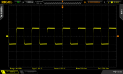
ΒΤW 100kHz square wave test with the new mirror transistors at a volume setting that I find plenty loud when on a sofa 4.5 meters away from my speakers. Its the same sound level that I would describe well loud before fatiguing for me on any headphones that are not mid-range recessed. 20kΩ series type switching log pot. Obviously the preamp remains fast enough for passing really high frequency pulses with such ease. 1.5MHz -3dB sine wave tested at that particular volume point.
Attachments
Pretty ideal amp for driving http://www.lundahl.se/wp-content/uploads/datasheets/1570_0xl.pdf and get a single ended to balanced with a dB raise
That is a very clean square wave for 100khz..
Regarding the SB716 (and 2SD756). I am planning to use them in Shaan's new PeeCeeBee V4H (high output) and +-60Vdc PSU.. Instead of BC546/BC556. I think 60Vdc is almost at the limit for those.
Have to do something about those "legs" right 🙂
Regarding the SB716 (and 2SD756). I am planning to use them in Shaan's new PeeCeeBee V4H (high output) and +-60Vdc PSU.. Instead of BC546/BC556. I think 60Vdc is almost at the limit for those.
Have to do something about those "legs" right 🙂
I populated all the parts on the board except the mosfets which I will do once I map the drill holes on the heat sinks.
Coming to the matched quad BC560, I have the following numbers mentioned by Tea-Bag in the kit.
1. 430 217 (hFE) presume its the hFE value
2. 430 222
3. 430 187
4. 430 181
So from the above list should I club 1+2 and 3+4?
Coming to the matched quad BC560, I have the following numbers mentioned by Tea-Bag in the kit.
1. 430 217 (hFE) presume its the hFE value
2. 430 222
3. 430 187
4. 430 181
So from the above list should I club 1+2 and 3+4?
That is a very clean square wave for 100khz..
Regarding the SB716 (and 2SD756). I am planning to use them in Shaan's new PeeCeeBee V4H (high output) and +-60Vdc PSU.. Instead of BC546/BC556. I think 60Vdc is almost at the limit for those.
Have to do something about those "legs" right 🙂
With such expanded frequency response to can even pass decent 100kHz pulses maybe thοse lower noise transistors should come little more to their own despite line level use. Because square root Hz noise integrates over bandwidth to RMS total energy. A higher noise per Hz amp can have less RMS noise if narrow than a lower noise one of much wider bandwidth. For example If you press your oscilloscope's bandwidth limit button its screen line gets thinner despite nothing changed in its noise spec. Those Japanese transistors are lower noise category but with less collector to base capacitance (Cob) than their respective lower noise European BC types. That's a good thing.
- Home
- Source & Line
- Analog Line Level
- Salas DCG3 preamp (line & headphone)