@ number9
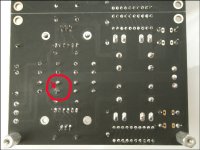
Maybe a discontinuity there? Check all connections between parts are good in the negative section's area with the DMM's continuity mode. Including LED to LED segments continuity and individual light up. Also check that J2 shows comparable RDS with J1 (Ohm mode measurement between D & S pins while the power is off).
Maybe a discontinuity there? Check all connections between parts are good in the negative section's area with the DMM's continuity mode. Including LED to LED segments continuity and individual light up. Also check that J2 shows comparable RDS with J1 (Ohm mode measurement between D & S pins while the power is off).
Attachments
Oops. 4 times compression:
Attachments
-
 IMG_1219_1.jpg540.4 KB · Views: 320
 -
 IMG_1218_1.jpg486.1 KB · Views: 285
 -
 IMG_1217_1.jpg501.7 KB · Views: 283
 -
 IMG_1216_1.jpg484.6 KB · Views: 316
 -
 IMG_1215_1.jpg535.3 KB · Views: 341
 -
 IMG_1214_1.jpg502.3 KB · Views: 328
 -
 IMG_1210_1.jpg651.6 KB · Views: 467
 -
 IMG_1209_1.jpg633.9 KB · Views: 494
 -
 IMG_1208_1.jpg673.1 KB · Views: 533
 -
 IMG_1207_1.jpg774.2 KB · Views: 595

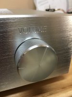
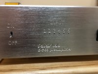
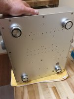
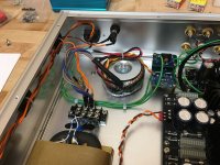
Ah, the detail benefits of a custom CNC chassis. Very good. I am also a lab now I see 🙂
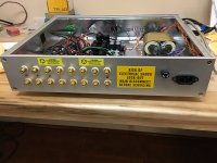
The cabling could have been a little shorter even. Mogami? Did you listen to the pre for more hours since first tests?
The cabling could have been a little shorter even. Mogami? Did you listen to the pre for more hours since first tests?
Still do try those 4.7k directly on the PCB line in connectors just in case. Some other problem must be at play if no change then. Build level problem. Maybe you misplaced R6 for R7? The rail voltages are sufficient. With more Vin-Vout from 18 VAC trafos there is better performance but your rails are still around 17VDC for a basically correct test. The DCSTB LED packs look bright enough, right?
*Don't place the audio system in danger. Even if not having gen & scope use 300HZ sinewave test signal from some digital device and a DMM in ACV mode to measure in vs out while debugging.
I found that my error, I had adjusted the dc bias using the hp outputs. Followed the correct procedure and the sound is much improved. Thanks for your help!
 Is the gain correct now too?
I think so it hovers around 00.0 + and - , is there any issue with the offset going negative at times?
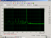
I'm back but not very much to report. I apologize for the false alarm but otherwise I'm happy! I just didn't manage to reproduce that 10kHz peak plot... Now it does not exist both in measurments and speakers. The fact is that my magic bus was kept in silence for more than a month due to sad occasions. All time record... Today I started it up to find that this noise has dissappeared. It's a pity I haven't kept the previous measurment. The whole thing reminded me a thought I've made about this phenomenon. I am side by side with the national telecomunications company. That means very good internet speeds but radio signal suffers. Radio had been kept silent also these days. I have to check it. Anyway, this evening I had a full listening session. Back to life!
Attachments
Ah, the detail benefits of a custom CNC chassis. Very good. I am also a lab now I see 🙂
The cabling could have been a little shorter even. Mogami? Did you listen to the pre for more hours since first tests?
I was sure that you must have a LAB in my house now! 🙂
Yes, I use Mogami 2330 and to be honest I thought I'll go for cupping links at the beginning. Unfortunately, never implemented that since I newer used that method in my past. So,skipped it that time too. I might go to short these coaxes by half soon, but I would like to test the whole thing for more time now. Will run it for 40 hours or close to see how it's behave after initial burn in.
I think so it hovers around 00.0 + and - , is there any issue with the offset going negative at times?
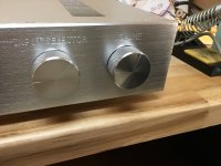
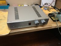
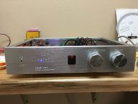
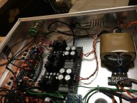
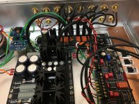
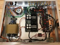
No issue. You put the servo op-amp back in its place after redoing the guide's offset trim step I believe. If you will think there is any other weirdness still going on, either electric or sonic, don't hesitate to ask again. Post some pics of the build sometime also.
I'm back but not very much to report. I apologize for the false alarm but otherwise I'm happy! I just didn't manage to reproduce that 10kHz peak plot... Now it does not exist both in measurments and speakers. The fact is that my magic bus was kept in silence for more than a month due to sad occasions. All time record... Today I started it up to find that this noise has dissappeared. It's a pity I haven't kept the previous measurment. The whole thing reminded me a thought I've made about this phenomenon. I am side by side with the national telecomunications company. That means very good internet speeds but radio signal suffers. Radio had been kept silent also these days. I have to check it. Anyway, this evening I had a full listening session. Back to life!
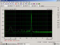
Good to know. RFI or a measurement artefact it should have been. If you will select 48kHz 131072 24bit in ARTA and push its signal gen several dB up it will show you even better results. You could try push the 50Hz and its harmonics a bit lower in the build if its because of mains wiring inside or outside crossing with signal cables. Could be due to a trafo's field of course. From nearby equipment even. Or a measurement loop issue if its done SE while your preamp is doubled up balanced. That would not be the case when connected to the balanced hi-fi system. Some external cards have ground lift DIP switch even.
I was sure that you must have a LAB in my house now! 🙂
Yes, I use Mogami 2330 and to be honest I thought I'll go for cupping links at the beginning. Unfortunately, never implemented that since I newer used that method in my past. So,skipped it that time too. I might go to short these coaxes by half soon, but I would like to test the whole thing for more time now. Will run it for 40 hours or close to see how it's behave after initial burn in.
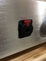
Soldering the wires is better, more robust and reliable, no need for periodic inspection to tighten connectors screws etc. But its also true its a small pain to rework soldered wires in a finished build. Pin terminated ends undo themselves more difficultly than finger twisted non tinned ends. Many of yours have pins and are only soldered to the jacks and pot so its easier to desolder and shorten from those ends than to cut from the other ends and terminate with pins again. Since you made a spacious and sturdy CNC box that everything is securely mounted inside, any rework can be done handily if ever. The 2330 is 35pF/Ft so its not a very big deal being somewhat longer than needed when there is no obvious issue to address, but less is more in general 🙂
Let us know your longer term subjective results then.
My "measurement set up" basicaly is my audio PC. Output signal is estimated at some 15mV pp. It has a PCI sound card that has been modified with output in mind. Now I'm doing some work on the input also. First pic is a ground loop and second EMI induced by transformers installed inside the PC. I gradualy address these issues. For DCG3 I've used shielded toroidals. The problem is that indeed I measure it in SE mode at the moment. I'm thinking to build P. Millett's or J. Didden's interface. Ground isolation and some gain.We'll see.Good to know. RFI or a measurement artefact it should have been. If you will select 48kHz 131072 24bit in ARTA and push its signal gen several dB up it will show you even better results. You could try push the 50Hz and its harmonics a bit lower in the build if its because of mains wiring inside or outside crossing with signal cables. Could be due to a trafo's field of course. From nearby equipment even. Or a measurement loop issue if its done SE while your preamp is doubled up balanced. That would not be the case when connected to the balanced hi-fi system. Some external cards have ground lift DIP switch even.
Attachments
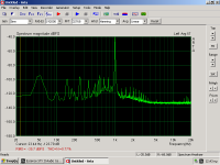
Set 48k Sampling (Fs) and highest FFT rate in ARTA. Also go to its audio device menu and select 24 bit wave. Make sure that the windows audio device driver is in sync set at 48K too. Run it again.
Look again into audio device and calibration menus in ARTA. Go to its generator's menu and up its output. Its impossible that a sound card can't give hundreds of mV at least. Usually much more.
Look again into audio device and calibration menus in ARTA. Go to its generator's menu and up its output. Its impossible that a sound card can't give hundreds of mV at least. Usually much more.
With all that noise in your PC you can't see anything cleanly isolated for a DUT but try with the above settings to make it run at its best. Loop the card from in to out with only a cable without a DUT first so to know its base best. So to can roughly mentally exclude its de facto harmonic noises and learn its own contribution in distortion spikes at several levels.
I set ARTA according your recomendations. The difference is that peaks are now sharper. I'll leave it like this for reference.
Unfortunately - or not 🙂 - the particular sound card cannot give high output. In fact it seems completely unsuitable for performing measurements. The real reason I'm trying all this is because I want to run speakers measurements through my audio system chain. I'll know if it is possible when I remove those noisy trafos.
Unfortunately - or not 🙂 - the particular sound card cannot give high output. In fact it seems completely unsuitable for performing measurements. The real reason I'm trying all this is because I want to run speakers measurements through my audio system chain. I'll know if it is possible when I remove those noisy trafos.
One day when you will win a moderate sum on football betting... 🙂
https://quantasylum.com/collections/frontpage/products/qa401-audio-analyzer
https://quantasylum.com/collections/frontpage/products/qa401-audio-analyzer
- Home
- Source & Line
- Analog Line Level
- Salas DCG3 preamp (line & headphone)