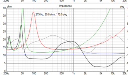
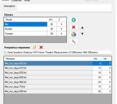
Here is the raw impedence. It now looks very similar to yours@Bmsluite - to erik's point above. Hoover over the Impedance pane of the VituixCAD 6-pack, right-click your mouse and select "Show Raw impedances". Right click again and select "Export image" to export an image of JUST the impedance pane and post that. That way it will be very clear to see. Sometimes if you export the whole 6-pack it is hard to see some of the details.
Attachments
Ok good because I just tried to move an Lpad to past the filters and I either get cancellation on the fore with regular or on the aft with it invertedEdit: just saw you don't use a shunting resistor anymore!
So it's ok now!
It will heat up to a dangerous level without you noticing it. The complete music spectrum current will flow through these two resistors (around 4 times the current that will produce useful sound, by the way).
It is really a terrible idea using very low value resistors and putting them at the unfiltered fullrange side of the crossover.
Attachments
Should I remove the shunt from the tweeter too? Seems this fixes cancellation up there as well. My directivity definitely takes a hit from this thoughEdit: just saw you don't use a shunting resistor anymore!
So it's ok now!
It will heat up to a dangerous level without you noticing it. The complete music spectrum current will flow through these two resistors (around 4 times the current that will produce useful sound, by the way).
It is really a terrible idea using very low value resistors and putting them at the unfiltered fullrange side of the crossover.
Attachments
No, just don't shunt the unfiltered signal!Should I remove the shunt from the tweeter too?

One suggestion: focus on on-axis response. Then try to fix phase. This will probably mess up your nice response so you'll have to work in iterations.
Then look at impedance. It's probably bad. Fix it. But this will mess you your nice response and phase so work in iterations.
Once you have a nice response, phase and impedance turn your focus to listening window and in room response. And... When you fix one of those it will mess up what you've done.
You can save 8 crossover variations at a time in VituixCAD. I tend to run through 24 to 32 variations. But I'm a lot less experienced with crossover networks than a lot of the guys posting, who might be able to come up with something in a few iterations because they have a pretty good idea of the value to start with and they know what each change is going to do to phase and impedance without having to "play around" as much.
Another note on phase is that each order of filter shifts the signal 45 degrees. So, a first order filter shifts 45, 2nd order filter shifts 90, 3rd is 135 and 4th is 180. So, if you're shifting the mid woofer at 2.5K by a 2nd order filter it shifts one way 90 degrees. If you shift the tweeter by a 2nd order filter it is shifting the signal the opposite way by 90 degrees which makes them 180 degrees out of phase so you often need a polarity flip to put them back in phase. It's more complicated than this when you add the acoustic slope to it, but keep in mind that sometimes you need different orders of filters to combine to be properly in phase. I have successfully mixed 2nd order on the mid woofer with 3rd order on the tweeter. Ultimately it's all about what they need to properly sum.
Yes! That is the right way - you have to try both ways.Setting it to normal I do get cancellation but inverting it fixes that.
Please post the drivers .txt files (both SPL and impedance) from VituixCAD here, I will try to make my version of crossover (hopefully better).
Bmsluite, if at some point you feel like you're running in circles and, as A4eaudio explains above, every time you fix something here something else gets screwed up there and you end up further away from your target, I for one would be happy to have a go at it if you share the data files and, if you want it to be your crossover design, at least I could point you in the direction of a filter topology that works and you can then try to optimize yourself.
The problem with a 3-way is that the number of possible topologies is exponentially larger than in a 2-way. You basically have two 2-way crossovers that interact with each other, and then there's the order of components in the bandpass, the option of three separate filters vs. a ladder arrangement...
The problem with a 3-way is that the number of possible topologies is exponentially larger than in a 2-way. You basically have two 2-way crossovers that interact with each other, and then there's the order of components in the bandpass, the option of three separate filters vs. a ladder arrangement...
I'm not quite ready to throw in the towel just yet. I have a little peak at the high that if i try to correct if screws up the room respones. I worry that on axis high frequency peak may make the system fatigueing to listen to on axis.
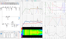
But if anyone wants to take a swing at this I am going to upload all my files in a zip folder. First time creating a zip folder so let me know if this actually works.
I think it would be good to compare what it should look like with what I am currently doing.
I did run the optimizer. It screwed it all up but it did at least verify that my L-C values were in the right ballpark this time. I had a different version of this that used a shunt after the filter for the tweeter. I may go back to that as I think the whole thing looks a bit better there.
Let me know what you find.
Attachments
I dug in my archives...

Back in 2012 I finished a 3-way design around the ZA14.

Overall response was pretty okay.

As was the proof of the pudding. Don't pay attention to the part under 200Hz, I didn't mind stitching the LF part for this measurement then.

This in an enclosure of 24cm wide and about 1m high. Just to point out that ZA14 isn't that hard to use and to give some inspiration.
Back in 2012 I finished a 3-way design around the ZA14.
Overall response was pretty okay.
As was the proof of the pudding. Don't pay attention to the part under 200Hz, I didn't mind stitching the LF part for this measurement then.
This in an enclosure of 24cm wide and about 1m high. Just to point out that ZA14 isn't that hard to use and to give some inspiration.
Bmsluite,
I could not believe I saw the "sagging mid range bandpass"
I had not seen that effect for decades.
The Radio IF transformers have a capacitor across the primary, and a capacitor across the secondary.
There is either magnetic coupling, or capacitor coupling . . . from the primary to the secondary.
When the primary and secondary are "over coupled", you get a frequency response that looks exactly like the problem curve in Post # 1.
Old "radio guys" will remember the over-coupled response.
If you need another example of a double peak like that, you only have to remember the impedance curve of a woofer that is in a ported enclosure.
As one who posted on the Multi-way threads, you probably already know this.
Perhaps those similar responses will help you solve the problem.
I always find it interesting when the same mathematics is found in many different circuits and different acoustics applications.
Efficiency, Q, insertion loss, multiple resonance, etc.
It was a lot of work in 1985 when I re-designed a 5 resonator 10 pole 500MHz Helical bandpass filter. I had the chief engineer for a mentor, an early filter software, and THE "Filter Bible" a giant book written by a Russian named Zverev, and published by Westinghouse.
I not only had to get non rippled frequency response, I also had to get good Group Delay response.
I considered using a different design for even better group delay, but the project had to move ahead, so I never did a second design (something you learn in engineering: bean counters, marketing, sales, and your customers needing the latest product . . . are all waiting).
Note: On Tubes / Valves threads, I never hear anybody mention "group delay" other than myself.
I think lots of posters on Multi-way do understand group delay, a credit to your group.
Happy problem solving!
Happy listening!
Perhaps the causes and math is completely different, but I doubt it.
Last edited:
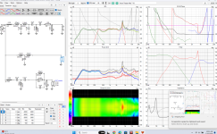
OK, this takes 15 minutes of my life 🙂 (but I have done hundreds of crossovers so far):Let me know what you find.
Mind you, this is far from optimal crossover! Among other things, in room response between from 2 kHz trough 4 kHz should be better.
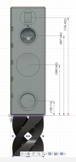
Edit: I just realized - you don't have "Y" values - distances between drivers! Crossover above would be correct ONLY IF the drivers are coaxial design! Please post distances between drivers!
Last edited:
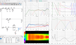
With the simulation model's 2.83V signal source impedance of 1m Ohm (1 milli Ohm), damping factor of 8,000,
this speaker is for operation with a solid state amplifier.
For a tube amp with damping factors typically ranging from 2 to 10, the results will be different.
this speaker is for operation with a solid state amplifier.
For a tube amp with damping factors typically ranging from 2 to 10, the results will be different.
I didn't pay attention that the voltage source is set to really low 1 mOhm impedance. But nothing changed if it is set up to 0.15 ohms (damping factor = 53), which is OK for almost any possible solid state amplifier. Loudspeaker usually are designed for use with solid state amplifier. Only handful are designed for tube amplifiers exclusively.
Last edited:
The box is not undersized, the manufacturer specs on that woofer measured differently from what was stated. I am going to print a new port with lower tuning in an attempt to smooth that out.
No! Take this advice:
just remove the port and make it closed. By my calculations, with your measured specs (which aren't far off from the datasheet), a closed box of the size you have, well stuffed and assuming Re=0.28 ohm will give you a Qtc = 0.77, which is not bad at all, and F(-3) = 46Hz, which again isn't bad for the box size and better than it looks given the gentler slope of the closed alignment, F(-10) is 28Hz (a reflex box with that F(-10) would have an F(-3) of about 37Hz). This is indeed a woofer intended for a closed box and it will work and sound best in one.
I have been able to use many different loudspeakers that are designed for use on solid state.
They do sound good on my tube amplifiers with low to moderate damping factors.
I have seen various commercial loudspeakers that are designed for the solid state market . . .
But Marketing also said that they work well with tube amplifiers.
Never miss a potential sale.
I just wanted to raise the damping factor issue.
Some threads in Tube / Valve discuss the issue.
One thing to consider is an amplifier with a 0.1 Ohm output impedance, that drives a single pole choke low pass filter, that drives a nominal 8 Ohm woofer that has 5 Ohms DCR. That does effect the total Effective damping factor of the complete system . . . 0.1 Ohms in series with 5 Ohms.
Ideal situations tend to last as long as the life of a Photon that has just hit its target.
Just my $0.03
No! Take this advice:
Exactly! That advice was given multiple times by multiple people already.
Having the resistor before the filters is going to give it the entire frequency spectrum and will cause it to have to dissipate a lot more heat. I would definitely put them after the filters and then redesign the filters. Having a single resistor after the filters changes the impedance that the filters see so their values will have to be different to get the same frequency response but this is much better practice.Having the resistor after destroys the whole thing. How is putting it before a fire hazard? As long as the resistor can take the wattage it will be fine. We use shunt resistors at work all the time. We are dissipating far more energy than this.
It might also still be useful to have a resistor in shunt with these since that creates an L-Pad, which leaves the filters seeing the same impedance as the driver. But at this point you're getting a lot of differing advice and I'm sure that's frustrating. Maybe we should go back to discussing the port and redesigning the box. hahahaha.
Yeah that looks better than what I made. I'll attach the baffle dimensions. I actually tried to change the y axis but it doesn't show up in my driver box. I'll post a snapshot of that too. For some reason it only gives me SPL and Z. I watched a video where someone was changing the y values on the drivers but my screen doesn't look like that.OK, this takes 15 minutes of my life 🙂 (but I have done hundreds of crossovers so far):
View attachment 1336053
View attachment 1336054
Mind you, this is far from optimal crossover! Among other things, in room response between from 2 kHz trough 4 kHz should be better.
Edit: I just realized - you don't have "Y" values - distances between drivers! Crossover above would be correct ONLY IF the drivers are coaxial design! Please post distances between drivers!
In answer to your port question, I will be trying out a lower tuned port just for fun (costs $12 to try, worth it for the fun). I will likely be plugging the port for most music and unplugging it when I want to crank it for some fun. I actually like this flexibility in the speaker and might build this into future designs even know I know this is likely anathema to most people on this forum. Sure is better than using a bass boost that just adds distortion.
Attachments
- Home
- Loudspeakers
- Multi-Way
- Saggy Bandpass filter