That together with the other bump at ~30Hz looks to me like an extremely undersized reflex box...The big hump at 70Hz suggests it's a Qtc of ~1,3, that will sound very boomy and imprecise, even if I'm very off with my estimate.

Yes, I thought that too.That together with the other bump at ~30Hz looks to me like an extremely undersized reflex box...
Bmsluite, could you share which drivers and box you are using? It would be easier to help you that way.
Also, I don't use VituixCAD, but as I understand it, driver offsets should be entered into the Dz parameter, otherwise the phase relationships will change and your actual response will differ substantially from your simulated one. Unless they are included in the measurements you took, in which case it's fine.
Also, I don't use VituixCAD, but as I understand it, driver offsets should be entered into the Dz parameter, otherwise the phase relationships will change and your actual response will differ substantially from your simulated one. Unless they are included in the measurements you took, in which case it's fine.
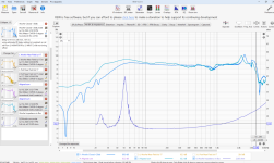
It's possible that the sag in the middle is related to the hump on each end. The "Q" of the filter is wrong. For the high pass filter section there will be a capacitor (68uf) in series then an inductor (2.7mh) in parallel. Changing the value of the inductor will change the Q and should both lower the hump on the end and raise the sag in the middle. Same goes for the low pass filter at the top. There is an inductor (.68mh) in series than a capacitor (6.8uf) in parallel. Changing the capacitor value there will change the hump and sag. This can get very complicated with a mid range driver since the closer you get with these two filters, the more they will affect each other. I also agree that the L-Pad should go after these filters (closer to the speaker). I also second the point that you have a phase issue with your woofer and mid driver. Try swapping the polarity on the woofer to see if it sums better. Though, the problem might just be the slope of the high pass filter on the mid woofer so it could get better once you correct the hump and sag.I notice any time I try to design a bandpass filter wide it starts to sag in the middle. Is this just the nature of a 4th order bandpass filter? I have to go up to a 6th or 8th to avoid the sag?
See purple oval in the filter section.
Ok, the impendences are showing now. I moved my shunt resistors and everything went to hell. That's ok though, I need 3rd orders for the bandpass so I needed to start over again anyways.
I also have all the axis measurements showing so that is fun.
The box is not undersized, the manufacturer specs on that woofer measured differently from what was stated. I am going to print a new port with lower tuning in an attempt to smooth that out. Quick question: Does changing the port out affect the near field frequency response of the woofer at all? Or does changing the port out just changed the port tuning? Obivoulsy the sum of these two will change but will the woofer response actually perform differently with a differently tuned port? I guess I'll find out soon enough....
I tried using the Vituix cad library of filters but they come in pretty crazy and require a lot of tuning so maybe just best used as a starting point. I do not know how to balance L-C. I just don't have the knowledge base for that. Does anyone have a simple way of explaining that to me that doesn't involve 400 equations I would need to master in my head?
The box is 3600 in cube. Currently it has a 10" port 4" diameter
Drivers:
Woofer - The SD is wrong on this site. It is 201 not 213
https://www.parts-express.com/Peerless-830667-8-Paper-Cone-SLS-Subwoofer-264-1102?quantity=1
Mid
https://www.madisoundspeakerstore.c...aph-audio-za14w08-5-aluminum-cone-mid/woofer/
Tweeter
https://www.parts-express.com/HiVi-...oysKHKeC4TtUbZd25hsEjnSrLuZ8m_MxoCfBwQAvD_BwE
Attachments
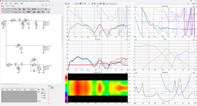
Ok, the impendences are showing now. I moved my shunt resistors and everything went to hell. That's ok though, I need 3rd orders for the bandpass so I needed to start over again anyways.
NO! You need the woofer 3rd order, the high pass of the mid DOES NOT!
The box is 3600 in cube. Currently it has a 10" port 4" diameter
Drivers:
Woofer - The SD is wrong on this site. It is 201 not 213
https://www.parts-express.com/Peerless-830667-8-Paper-Cone-SLS-Subwoofer-264-1102?quantity=1
Get rid of that port, that driver with a Qts of 0,66 is for sealed!
E: 1 Ohm impedance minimum! 😳 I've got amps that can handle that - but most will not like that at all!
I definitely would not try to tune this woofer lower. I think it's already too low now. They're looking at the wrong specs, which is the same thing I was doing on that other thread when I was trying to get you to make a bigger box and bigger port. I can't find your impedance measurements now but I thought I saw the box was tuned around 30Hz (the lowest point between the 2 peaks on the impedance chart). This woofer has an FS of 42Hz so you're tuning really low. When I finally got the correct specs and ran the numbers I think it was calling for a smaller box but I can't remember now.
Why 3rd order the woofer and the mid? I inverted the woofer.NO! You need the woofer 3rd order, the high pass of the mid DOES NOT!
Get rid of that port, that driver with a Qts of 0,66 is for sealed!
E: 1 Ohm impedance minimum! 😳 I've got amps that can handle that - but most will not like that at all!
I honestly know nothing about the phase alignment. Can you trace out and give me an idea of where I want the phase to be? I need it explained like I'm a 7 year old with an engineering degree lol. I don't know what to even look at.
Picture is just where I am so far
Attachments
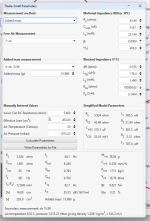
Yeah, enough with the port talk. I am not rebuilding this enclosure. Here are the actual measured parameters.
Have you ever heard of 'make a prototype'? And a Qts of 0,7 - if you still want to go ported instead of sealed/TML/TQWT/OB then you're beyond all help. Literally wasted time and effort.
I'm going to try to tun it lower just to see what happens.
"Yeah, so many ppl tell me water only flows downwards, but mine runs uphill!"
ICG,
So you literally just asked if I had heard of prototypes and then talked trash about me trying out a different prototype part? Are you serious? Can you hear yourself?
So you literally just asked if I had heard of prototypes and then talked trash about me trying out a different prototype part? Are you serious? Can you hear yourself?
So you literally just asked if I had heard of prototypes and then talked trash about me trying out a different prototype part? Are you serious? Can you hear yourself?
You refused to do another enclosure. And you still claim your water flows uphill. Sorry, I'm out.
You don't have to, just remove the port and make it closed. By my calculations, with your measured specs (which aren't far off from the datasheet), a closed box of the size you have, well stuffed and assuming Re=0.28 ohm will give you a Qtc = 0.77, which is not bad at all, and F(-3) = 46Hz, which again isn't bad for the box size and better than it looks given the gentler slope of the closed alignment, F(-10) is 28Hz (a reflex box with that F(-10) would have an F(-3) of about 37Hz). This is indeed a woofer intended for a closed box and it will work and sound best in one.I am not rebuilding this enclosure.
You can also just stuff it tightly with clothes to test the sealed enclosure sound. If you like it you could make a closed cell foam plug, looks nicer.just remove the port
When Qts gets above about 0.6, you have to tailor the fill to adjust for the ripple in the passband. I have successfully used stuffed vented boxes with driver Qts to 1.3, so it can be done.
I can print a plug. I can model it up really fancy. I planned to do that anyways just to see what happens to the response.You don't have to, just remove the port and make it closed. By my calculations, with your measured specs (which aren't far off from the datasheet), a closed box of the size you have, well stuffed and assuming Re=0.28 ohm will give you a Qtc = 0.77, which is not bad at all, and F(-3) = 46Hz, which again isn't bad for the box size and better than it looks given the gentler slope of the closed alignment, F(-10) is 28Hz (a reflex box with that F(-10) would have an F(-3) of about 37Hz). This is indeed a woofer intended for a closed box and it will work and sound best in one.
Attached is the woofer response by itself. Its not bad at all even with the hole in it. Will be interesting to see the difference between it having it plugged and it not having a giant port hole in it.
Attachments
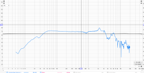
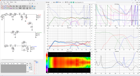
Alright so here is the port closed vs ported (ported is the aligned sum of the woofer and port). Idk, none of them are perfect. I'll likely keep it sealed for regular use and just stick the port in if I want to crank it up some day.
It doesn't seem like its going to affect the crossover. At the XO frequency nothing changes.
It doesn't seem like its going to affect the crossover. At the XO frequency nothing changes.
Attachments
For starters, that sealed measurement looks great and will probably sound much more balanced but it's cool that you have the option to change back and forth. It could yield some fun. Ignore the people who are trying to micro-manage your project. That's not helpful at all.Why 3rd order the woofer and the mid? I inverted the woofer.
I honestly know nothing about the phase alignment. Can you trace out and give me an idea of where I want the phase to be? I need it explained like I'm a 7 year old with an engineering degree lol. I don't know what to even look at.
Picture is just where I am so far
OK. For phase alignment, you're going to be looking at the points where the drivers crossover (plus above and below that point). From woofer to mid you're going at about 350Hz. From mid to tweeter you're at about 2600Hz. To check if they are in phase at the crossover point, they should sum about 6db louder at that point. So the woofer and the mid-woofer should both be at -6db at that crossover point and the measurement that you take of all of them together should sum there to be 6db higher. Same with the mid woofer and tweeter. Sometimes it takes different combinations of 1st, 2nd, 3rd or 4th order filters to get them to properly sum.
When you're looking at just the mid woofer frequency response and parts of it are louder by itself than they are when the woofer and tweeter are playing then you have a phase problem. In essence, nothing should get quieter when there are more speakers playing. So if part of the low woofer's frequency response is louder by itself than when the mid is also playing then you have a phase problem. It's similar to when you flip the polarity on the tweeter and there is a massive hole at the crossover point. That means it's out of phase.
In your earlier graph there was an area around 250Hz-1Khz where the mid woofer was louder by itself than with the other drivers. That means that the phase is incorrect and they are cancelling each other out. So you will need a different "order" of filter there along with the possibility of polarity inversion. Your last graph looks a lot better and they seem to be summing properly. I'm doing my best to explain this. Let me know if you have questions.
....and much higher, some RS 1286 I still have are in the 2.86 - 3+ range!with driver Qts to 1.3
- Home
- Loudspeakers
- Multi-Way
- Saggy Bandpass filter