No, it is not in the nature of the bandpass filter - just the L-C values you choose are not optimal. Also, the midrange filter is not 4th order, but a symmetrical 2nd order.
There's a big problem with the phase. At the lower XO of the midrange the sum is a lot lower than the midrange on itself.

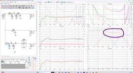
The bass isn't dropping off fast enough and the phase error goes over 1,5 octaves, that will sound bad - you have fix that, no doubt.
I don't like peak of the mid at 4,5k either because the ear is very sensitive at that range.
The bass isn't dropping off fast enough and the phase error goes over 1,5 octaves, that will sound bad - you have fix that, no doubt.
I don't like peak of the mid at 4,5k either because the ear is very sensitive at that range.

From another thread:
https://www.diyaudio.com/community/threads/why-is-crossover-calculator-spread-always-fixed.407805/
"The Great Sound Stereo Speaker Manual states: "in the bandpass circuit, you must make a slight calculation. . . . because the components interact some adjustments should be made to the standard values. . . . In effect, you calculate the values for a slightly narrower band of frequencies than the desired band."
It also uses the reciprocal of the ratio of the upper to lower cross points to add to the inductor and subtract from the capacitor standard values. This is a basic method based on nomographs though, and things have progressed since then. As others said, it's now common to use a simulator to get these dialed in (using actual impedance data for the drivers)."
What I haven't seen is the mid impedance curve.
That peak is part of the mid frequency response. It breaks up past 3k really bad. It's a zaph 5" aluminum cone.There's a big problem with the phase. At the lower XO of the midrange the sum is a lot lower than the midrange on itself.
View attachment 1335347
The bass isn't dropping off fast enough and the phase error goes over 1,5 octaves, that will sound bad - you have fix that, no doubt.
I don't like peak of the mid at 4,5k either because the ear is very sensitive at that range.
Only other option is to cross is more aggressively but I don't know how to do that with a band pass. I tried adding another cap but it just tore the thing the response to shreds.
It's loaded in there. It has that little 4500 Hz peak in itWhat I haven't seen is the mid impedance curve.
Can you show me what a band pass filter looks like that is more aggressive?There's a big problem with the phase. At the lower XO of the midrange the sum is a lot lower than the midrange on itself.
View attachment 1335347
The bass isn't dropping off fast enough and the phase error goes over 1,5 octaves, that will sound bad - you have fix that, no doubt.
I don't like peak of the mid at 4,5k either because the ear is very sensitive at that range.
This is just inductor-cap-ground to cap-inductor-ground. The circuit is there on the left of the original image
What I haven't seen is the mid impedance curve.
It's loaded in there. It has that little 4500 Hz peak in it
Here is an impedance curve on a three-way I built a few months ago. I think erik's point is that your impedance looks nothing like this.
The phase problem is mainly the low pass filter of the bass, but you likely need to change both. Don't view it as a band pass filter but a low pass and a high pass filter of the bass and a high pass filter of the midrange. The options are to use a different pair of L/C values, absorption filter or going for 3rd order for the bass LPF while keeping the 2nd order HPF for the mid. The acoustical slopes matter, not the electric ones.Can you show me what a band pass filter looks like that is more aggressive?
This is just inductor-cap-ground to cap-inductor-ground. The circuit is there on the left of the original image
About the standard values: That often still applies but the combination of two or 3 C can often reach needed values and the coil can be partly be unwind if you absolutely need to get a different inductance. Of course other alternatives are preferred first though.It also uses the reciprocal of the ratio of the upper to lower cross points to add to the inductor and subtract from the capacitor standard values. This is a basic method based on nomographs though, and things have progressed since then. As others said, it's now common to use a simulator to get these dialed in (using actual impedance data for the drivers)."
Uhm, no, the picture only shows the electrical filter characteristics, not the impedance.It's loaded in there. It has that little 4500 Hz peak in it
OK, I thought I heard somewhere not to use more than second order on the low pass for the woofer but I've read so much stuff that I don't remember what's what anymore. I'll toss a 3rd order on the Woofer tommorrow.
I'll post up tomorrow morning with the impendence data. I'll take the impendence measurements again just to be sure. Only takes about 5 minutes.
I'll post up tomorrow morning with the impendence data. I'll take the impendence measurements again just to be sure. Only takes about 5 minutes.
You could also try an absorption circuit but it is not a single peak of the bass. Also, it depends on the situation. 3rd order in the bass can become expensive and the Qtc will increase. The woofer is obviously already high Qts/Qtc and likely cheap so that might not be feasible but is probably the best solution for the problem. Do you want to build this speaker or is that an exercise to learn about crossovers?OK, I thought I heard somewhere not to use more than second order on the low pass for the woofer but I've read so much stuff that I don't remember what's what anymore. I'll toss a 3rd order on the Woofer tommorrow.
BIG PROBLEM- move the lpad around! The shunt resistors should NOT be before the xover ever as you are shunting full bandwidth power with those 2 resistors across your amplifier outputs. Most people place the series R fore or aft, but the shunt should ALWAYS be after.
This is why the impedance of the system registers low and flat.
This is why the impedance of the system registers low and flat.
What I still don't see is the impedance curve of JUST the midrange. I see the transfer function, which is hammock shaped, but the mid impedance curve could explain at least some of that.
@Bmsluite - to erik's point above. Hoover over the Impedance pane of the VituixCAD 6-pack, right-click your mouse and select "Show Raw impedances". Right click again and select "Export image" to export an image of JUST the impedance pane and post that. That way it will be very clear to see. Sometimes if you export the whole 6-pack it is hard to see some of the details.
That’s what I thought… and indeed, below 1Ω 😱you are shunting full bandwidth power with those 2 resistors across your amplifier outputs.
In my experience the ZA14 needs either a ‘sink hole’ at the resonance peak or a well designed 3d or 4th order lowpass to get rid of the metal cone resonance playing up. You didn’t succeed at that enough, to my humble opinion.
Furthermore: try a ladder setup for the mid and tweeter. Often phase relationship between both will get better that way.
I can promise you, the bass of that speaker will not be high end. 😉 The big hump at 70Hz suggests it's a Qtc of ~1,3, that will sound very boomy and imprecise, even if I'm very off with my estimate.Both. I'm a nerd with not a lot of money who has a taste for high end audio and cars. This scratches two itches.
- Home
- Loudspeakers
- Multi-Way
- Saggy Bandpass filter