Many many years ago I read this described as "Resistive Reflex" > actually regarding an Advent speaker model.Personally made small high Qtb/c vented boxes ~aperiodic using stuffing and dialing it in via critical damping for a sort of a best of sealed/vented compromise.

Why would you say that the L-C values are not optimal. The aim is to achieve a specific target acoustic response function. If that has been achieved, then for the natural driver response in question, I would have thought that the computed L-C values are the correct/optimal ones. They just happen to be applying a little bit of equalization as well as the necessary filtering (two jobs completed for the price of one circuit).No, it is not in the nature of the bandpass filter - just the L-C values you choose are not optimal.
Last edited:
That's a very good point. There is around 2dB of mismatch. The off-axis radiation can be expected to be adversely affected in that 300–600Hz frequency range, which is not ideal.There's a big problem with the phase. At the lower XO of the midrange the sum is a lot lower than the midrange on itself.
View attachment 1335347
The impedance curve plotted by VituixCAD seems to be unusually low, if I am seeing things correctly. Have the driver impedance response functions been correctly included in the model?What I haven't seen is the mid impedance curve.
There is a really large, potent breakup peak at 9kHz in the Zaph Audio ZA14W08 5" Aluminum Cone Mid/Woofer. The peak at 4.5kHz is much, much smaller and more highly damped.That peak is part of the mid frequency response. It breaks up past 3kHz really bad. It's a zaph 5" aluminum cone.
As you mentioned, increasing the order of the low-pass section of the band-pass filter is what needs to happen. You should have added an inductor to change the low-pass filter from 2nd-order to 3rd-order, rather than adding a capacitor as you did.Only other option is to cross is more aggressively but I don't know how to do that with a band pass. I tried adding another cap but it just tore the thing the response to shreds.
Try adding an inductor and see what results you can obtain.
You may also need to increase the order of the high-pass filter that is on the tweeter. However, this may not be needed in practice, as asymmetric crossover slopes can work quite well in many situations.
There is a simple reason why the present impedance curve looks nothing like that.Here is an impedance curve on a three-way I built a few months ago. I think erik's point is that your impedance looks nothing like this.
Check the values of the first two resistors on the midrange's filter circuit:
One is 0.56 ohms and the other is 0.47 ohms! These add up to 1.03 ohms, which forms the dominant impedance of the three-way filter network, as the other drivers are all connected in parallel.
To fix this issue, the two resistors need to be increased by about a factor of 10, and the filter components recomputed.
They are only a starting point, and they save the work of having to add in all the components one by one. Their values are computed based on a selected constant resistance as the filter load. For a bandpass filter especially, that's unlikely to get you in the right ballpark.I tried using the VituixCAD library of filters, but they come in pretty crazy and require a lot of tuning so maybe just best used as a starting point.
That's where VituixCAD's circuit optimizer comes into play. It should be able to do a reasonable sort of job.I do not know how to balance L-C. I just don't have the knowledge base for that.
I suggest only permitting the components on the midrange to be varied during the initial optimization process. Those on the woofer and tweeter should remain fixed (the appropriate checkboxes left unchecked). That will help to force VituixCAD's optimizer to work on the frequency range you want it to work on.
Sorry to insist on this point and apologies if you've already replied to it and I missed it, but it's important, not much point optimizing the crossover if the offsets aren't included...Also, I don't use VituixCAD, but as I understand it, driver offsets should be entered into the Dz parameter, otherwise the phase relationships will change and your actual response will differ substantially from your simulated one. Unless they are included in the measurements you took, in which case it's fine.
I would not place a 1.2 ohm resistor in parallel with the midrange driver. That's why you get such a low value for the minimum impedance.Ok, the impedences are showing now. I moved my shunt resistors and everything went to hell. That's ok though, I need 3rd orders for the bandpass so I needed to start over again anyways.
3600 cubic inches comes in at around 59.0 litres, which is a reasonable size box. For your driver, Fs = 42.2 Hz, Vas = 26.3 litres, and Qts = 0.66. That is a high value of Qts, so this driver is better suited to a closed box than a vented box. Using your box size and vent tuning, the VituixCAD vented box simulation produces the following:The box is 3600 in cube. Currently it has a 10" port 4" diameter
If we switch to a closed box of the same volume, we obtain the following low-frequency response:
The above response does not have the 2dB peak that is produced by the vented box alignment. However, the low-frequency −3dB point obtained with the closed box is 47.6Hz, rather than the much lower 31.3Hz obtained with the vented box.
The +2dB peak in the vented box response could of course be tamed with a slight reduction of bass output using the bass control on an amplifier. Most of the bass extension would then still be maintained, but the peak would be largely ameliorated. That may be an acceptable solution for your particular circumstances.
Of course, if you doubled the enclosure volume from 59.0 litres to 118 litres, you could alter the low-frequency alignment to reduce the size of the peak in the bass. An example of what might be possible using this approach is shown below. This type of design follows Thiele's Chebyshev low-frequency alignments.
After you have spent all that time building the enclosure, I can fully understand that sentiment.I am not rebuilding this enclosure.
Your 10-inch vent length is quite long, with the potential to produce port resonance. Maybe it's worth considering a shorter vent, which could be easily achieved with a vent 3 inches in diameter.I'm going to try to tun it lower just to see what happens. Cost me $12 worth of filament to try. No big deal.
In the VituixCAD simulations, the peak in the bass response is 1.8dB in height for a vent tuning of 32.5Hz. If we lower the vent tuning to 27.4Hz, we reduce the size of the peak down to around 1.0dB. The low-frequency response will look something like the following. Note the increase in vent length is very large if a 4-inch vent diamter is used, so it would be strongly recommended to reduce the vent diameter to 3 inches, which is still quite generous.
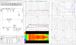
Look at the top left graph (SPL) from the post #1. Between 350 Hz and 1 kHz total output is up to 2 dB lower than the midrange output alone - some partial cancelation between woofer and the midrange is in effect. That is courtesy of not optimal L-C values. Also, total output between 2 Khz and 3 kHz is 1 dB higher, because of the not optimal L-C values.Why would you say that the L-C values are not optimal.
That is only one criterion, there are others too - see above.The aim is to achieve a specific target acoustic response function. If that has been achieved, then for the natural driver response in question, I would have thought that the computed L-C values are the correct/optimal ones.
I have looked at the top left graph of SPL, as you have suggested. And I recognize that there are different design criteria coming into play when desiring to evaluate "optimality".
I still don't think that the problem as noted can be ascribed simply to non-optimal L-C values. After all, if the target function is for a flat on-axis response, then those values are entirely reasonable under those circumstances.
In addition, the filtered response of the midrange driver response is almost textbook flat in its passband. So, by any stretch of the imagination, the L-C components in and of themselves could be regarded as being "optimal" in that particular sense. The peaking at the two ends of the electrical response function is merely an attempt by the optimizer to modify the acoustic response of the driver to achieve the overarching goal of flatness.
Of course, I also understand that the fact that the response of the midrange is below that of the summed response is indicative of non-complementary characteristics in the various filtered acoustic responses. That's the part that is not optimal, as in the design itself is sub-optimal in that respect, not the midrange's L-C values in and of themselves. Hopefully I've been able to present a cogent discourse herein.
Last edited:
There is a simple reason why the present impedance curve looks nothing like that.
Check the values of the first two resistors on the midrange's filter circuit:
View attachment 1335783
One is 0.56 ohms and the other is 0.47 ohms! These add up to 1.03 ohms, which forms the dominant impedance of the three-way filter network, as the other drivers are all connected in parallel.
To fix this issue, the two resistors need to be increased by about a factor of 10, and the filter components recomputed.
No, the 470milliohm resistor needs moved to AFTER the xover. That is (or was if he's fixed it) the main problem. Then he can worry about values being higher. Right now he has a fire hazard on his hands in this image.
No, they are not. The simple fact of partial cancelation of woofer and midrange is the evidence for non-optimal L-C values. Flat on-axis must not relay on partial cancelation - it is wrong, as simple as that.if the target function is for a flat on-axis response, then those values are entirely reasonable under those circumstances.
They are included in the measurementBmsluite, could you share which drivers and box you are using? It would be easier to help you that way.
Also, I don't use VituixCAD, but as I understand it, driver offsets should be entered into the Dz parameter, otherwise the phase relationships will change and your actual response will differ substantially from your simulated one. Unless they are included in the measurements you took, in which case it's fine.
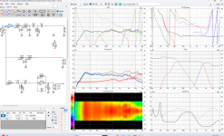
Setting it to normal I do get cancellation but inverting it fixes that. See below.No, they are not. The simple fact of partial cancelation of woofer and midrange is the evidence for non-optimal L-C values. Flat on-axis must not relay on partial cancelation - it is wrong, as simple as that.
Attachments
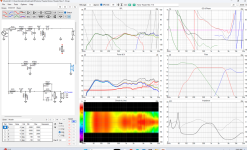
Having the resistor after destroys the whole thing. How is putting it before a fire hazard? As long as the resistor can take the wattage it will be fine. We use shunt resistors at work all the time. We are dissipating far more energy than this.No, the 470milliohm resistor needs moved to AFTER the xover. That is (or was if he's fixed it) the main problem. Then he can worry about values being higher. Right now he has a fire hazard on his hands in this image
Attachments
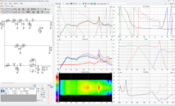
I have heard that you shouldn't mix odd and even order filters on a bandpass though. Is there merit to this?There is a really large, potent breakup peak at 9kHz in the Zaph Audio ZA14W08 5" Aluminum Cone Mid/Woofer. The peak at 4.5kHz is much, much smaller and more highly damped.
As you mentioned, increasing the order of the low-pass section of the band-pass filter is what needs to happen. You should have added an inductor to change the low-pass filter from 2nd-order to 3rd-order, rather than adding a capacitor as you did.
Try adding an inductor and see what results you can obtain.
You may also need to increase the order of the high-pass filter that is on the tweeter. However, this may not be needed in practice, as asymmetric crossover slopes can work quite well in many situations.
Lowering the tuning frequency and reducing the port size is what I am going to try, however, one guy totally lost his chill when I suggested this lol. I'm still going to do it though. I'm going to a 29hz tune with a 3.75" port. I forget the length but I already modelled it and will print it overnight on Sunday. Printer is currently doing prints for actual paid jobs in the shop right now.Look at the top left graph (SPL) from the post #1. Between 350 Hz and 1 kHz total output is up to 2 dB lower than the midrange output alone - some partial cancelation between woofer and the midrange is in effect. That is courtesy of not optimal L-C values. Also, total output between 2 Khz and 3 kHz is 1 dB higher, because of the not optimal L-C values.
That is only one criterion, there are others too - see above.
How is putting it before a fire hazard?
Edit: just saw you don't use a shunting resistor anymore!
So it's ok now!
It is really a terrible idea using very low value resistors and putting them at the unfiltered fullrange side of the crossover.
- Home
- Loudspeakers
- Multi-Way
- Saggy Bandpass filter