@PMA Can you share something about the SMPS that your used - why that model etc
You mentioned in the first post that the switching noise is above the audio range, but did you use a filter after the SMPS?
Thank you in advance for any information you can share
(edit because make and model of SMPS is in the first post)
You mentioned in the first post that the switching noise is above the audio range, but did you use a filter after the SMPS?
Thank you in advance for any information you can share
(edit because make and model of SMPS is in the first post)
Last edited:
Throw in a cshunt .option around 1pF and you'll start seeing real ghosts in any sym you ever made .There aren't many other rules that can scramble any simulation approaching it to a dire reality more than this one.50 W AB(80mA) 4 ohm THD 20kHz -0.0002%

No, there is no additional filter behind the SMPS. The only and important addition is the reverse voltage (parallel) blocking diode, see the image below. Output wideband noise is attached as well (2RC filter mentioned is only to suppress scope FFT aliases).@PMA Can you share something about the SMPS that your used - why that model etc
You mentioned in the first post that the switching noise is above the audio range, but did you use a filter after the SMPS?
Attachments


.OPTION cshunt=1e-12...
Usually I use 1e-15 to get shiny good looking results but every time I go past 1e-13 i get in trouble with any sym...True circuits can easily approach the 1e-12 condition if careless.1e-13 would be an acceptable intermediate value for a very good pcb design.Cshunt option though is indiscriminate ...it ads capacitance between every nodes in the circuit so it should be used with caution as some nods can have up to 10pF while others go way below 1e-15 .That is why you'll see real circuits having 100pF where in simulation you're using only 5pF compensation. As a side note I don't trust soundcard thd measurements done over 2khz as they see THD plus the noise they can measure while the true noise is way higher than what a soundcard can see and a scope can easily point out that(just try measuring a gprs signal interference spectrum and for that I give PMA all the credit for preferring j-fet opamps , but that's just another topic....
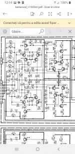
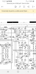
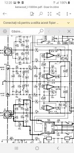
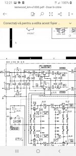
For EMI prevention in bjt input amplifiers I'd point out to bridged kenwood's best amplifiers input sections like Kenwood L-1000M or KM-X1000.I had the occasion to hear a km-x1000, one of the few 90's kenwood amplifiers to receive the Dolby THX certification.That's a Beast!I always preffered Kenwood's best designs over any other company not only for I had some of their best amp and never heard anything more neutral, but also because they had a better sense of electromagnetic interference as they were also comissioned to service USA army com equipment for decades.
Usually I use 1e-15 to get shiny good looking results but every time I go past 1e-13 i get in trouble with any sym...True circuits can easily approach the 1e-12 condition if careless.1e-13 would be an acceptable intermediate value for a very good pcb design.Cshunt option though is indiscriminate ...it ads capacitance between every nodes in the circuit so it should be used with caution as some nods can have up to 10pF while others go way below 1e-15 .That is why you'll see real circuits having 100pF where in simulation you're using only 5pF compensation. As a side note I don't trust soundcard thd measurements done over 2khz as they see THD plus the noise they can measure while the true noise is way higher than what a soundcard can see and a scope can easily point out that(just try measuring a gprs signal interference spectrum and for that I give PMA all the credit for preferring j-fet opamps , but that's just another topic....
For EMI prevention in bjt input amplifiers I'd point out to bridged kenwood's best amplifiers input sections like Kenwood L-1000M or KM-X1000.I had the occasion to hear a km-x1000, one of the few 90's kenwood amplifiers to receive the Dolby THX certification.That's a Beast!I always preffered Kenwood's best designs over any other company not only for I had some of their best amp and never heard anything more neutral, but also because they had a better sense of electromagnetic interference as they were also comissioned to service USA army com equipment for decades.
Attachments
Last edited:
I'd actually welcome PMA for copying well known designs than just arbitrarily reinvent the wheel as many people did here(myself included) on the grounds of being original because the audio field already has a very rich legacy to preserve and a samurai katana has nothing really new to improve in it.
Simulation instruments are fantastic if well used and I still have a lot to grasp on it , but what is essential to be simulated can be easier to learn after trying some real world designs that were more or less successful and see the difference.
Just load lt spice on two different computers run the same asc file for a few times and you'll see oddly that you get different results even after a reboot on the same computer .Then ask yourself why it happens and you might get the sense of why any electronic equipment manufacturer has a test department and adjust the real world designs accordingly to the taken measurements and other rules that aren't very easy to sim .Well...I run my files on a 12 years old computer with limited ram and sp7 ...so maybe I'm at fault here so ...don't use too old non updated equipment 🙂
I forgot saying something really interesting I saw only in KM-X1000.It has two power transformers, but not one for each channel, instead it's using one transformer to supply the positive rail and the other to supply the negative rail as when used in bridged mode it helps delivering instantaneous power from both amplifiers preventing hysteresis effects delay due to core saturation charging the filtering capacitors too slowly. It also comutes the power line voltages to a lower value in bridged mode which is the professional way to go and I haven't seen it in other equipment, but you may point me to other simillar designs I ignored checking and I'd be happy seeing them. Also all venerable kenwood amps are using e+i transformers which I heard are better at preventing saturation than toroids just higher emi noise so they needed good shielding.
... and they have much lower primary/secondary stray capacitance and make measurably better preamp/amp combo if single-ended link is used, better S/N and lower residual mains multiples related noise due to cable shield currents.Also all venerable kenwood amps are using e+i transformers which I heard are better at preventing saturation than toroids just higher emi noise so they needed good shielding.
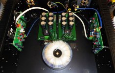
I have re-measured this amplifier with linear power supply, 2x25V, capacitor bank 2x14100uF per channel, transformer with separate secondary windings for two channels. My theory about differences in distortion between operation with SMPS and linear PSU has failed 🙂, distortion results are almost equal.
Attachments

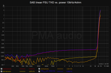

So far prevailing theory, that (good enough) PS is not affecting distortion numbers, is confirmed again. 🙂My theory about differences in distortion between operation with SMPS and linear PSU has failed 🙂, distortion results are almost equal.
Most intriguing question is why different PS, resulting in same distortion figures, sometimes result in different sounding amplifier. To exclude all sorts of supernatural hearing beings, present on this forum, there are knowledgeable members with vast experience and top equipment at their disposal, who discuss such matters. To name few, Jack Walton and audioeXpress team from the legendary power supplies test. I noticed Jack mentioning several times that they could hear rail harmonics by “bad” PS as “sound smearing” and rail harmonics were introduced by bad PS transient response.
So, it could be useful to not check PS/amp with “soft” stationery signal as 1 kHz sinewave is, but to apply big square wave signal and observe rail response and harmonics for any mayor difference between different PS. IMO, it could tell a lot about how good PS is for an audio duty.
OTOH, we could simply forget all this and just enjoy the music. 😀
My two last DIY SS amps are SMPS powered and work great: Alpha Nirvana (ClassA) and AEM6000 (AB).
No more clunky linear PSU for me, there is no way back, thank you.
No more clunky linear PSU for me, there is no way back, thank you.
To name few, Jack Walton and audioeXpress team from the legendary power supplies test. I noticed Jack mentioning several times that they could hear rail harmonics by “bad” PS as “sound smearing” and rail harmonics were introduced by bad PS transient response.
Thank you, it is interesting, but did they do a level matched double blind test? More and more, now almost completely, I do not believe any good "audiophile" story that is not supported by a valid DBT test result, regardless the great names behind. Please do not ask me to tell names, anyway, there has been a famous thread of 3 instalments during 20 years, good stories, big names, but ....
It is easy to get confused and very difficult not to be biased, even if unintentionally. And most of the great guys have permanently refused doing a DBT.
I doubt it was a DBT test.
I don’t take all claims from great names at face value but they are food for taught. Just looked up last comment on the matter made by Jack Walton.
https://www.diyaudio.com/community/...ith-ic-voltage-regulators.359652/post-6329354
It was a Linear Audio article and team, not from audioExpress.
I don’t take all claims from great names at face value but they are food for taught. Just looked up last comment on the matter made by Jack Walton.
https://www.diyaudio.com/community/...ith-ic-voltage-regulators.359652/post-6329354
It was a Linear Audio article and team, not from audioExpress.
I agree. They may give a good hint, but let's keep a critical thinking based on education and knowledge 🙂.I don’t take all claims from great names at face value but they are food for taught.
It prevents SMPS failure from reverse voltage coming from the amp if one of the supplies starts much earlier than the other one. Yes cathode to +. Keep those diodes, they will save the supply modules and the amp as well. For more detailed explanation, please google on reverse voltage SMPS blocking diodes. BTW, such diodes are good to use even with the linear PSU, placed behind the fuses. Same reason, in case that only one fuse is burnt they will save the amp, any amp.
Forgive me for a couple of silly questions.
In post #1, you mentioned :
"As a power supplies I used Mean Well RS-100-24 modules, one per channel."
According to the manufacturer, this is single output 24V 5A.
The schematics suggest the amplifier uses splitt rails.
So I guess you are wiring the output as +/-24V and the supplies are commonly used by both amplifier channels ?
If yes, that also suggests that the the SMPS outputs are not connected to mains Neutral or Earth, correct ?
Also I guess you have on-board caps on the amplifier.
Can the SMPS cope with additional caps on its output ?
Thx in advance,
Patrick
Hello Patrik,
Yes the 2 SMPS (1 x 24V each) supplies were used for 2 channels, so there is a common ground and common rails for both channels. If both channels are under full swing into 4ohm loads, this will be at the current limit. Each of the supplies was set to 27Vdc output voltage by the trim pot just next to the supply output terminals.
The SMPS outputs are not connected to PE. The input PE screw of the SMPS is connected to chassis and PE. Analog ground of input insulated connectors is connected to chassis via C or C//R combination (47nF, R as you like it) to prevent HF floating.
There are only 100uF rail bypass capacitors on the PCB boards. The SMPS's should not be loaded with additional several thousands uF capacitor banks, manufacturers do not recommend such operation, there is a risk of reduced lifetime and failure.
-------------------------
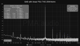
I have some new measurements using my new toy, E1DA Cosmos ADC
https://e1dashz.wixsite.com/index/cosmos-adc
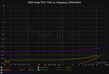
It is interesting to see that in a class AB amplifier with low distortion front-end, all the distortion is solely related to the output stage crossover distortion. Please note the difference in distortion with 1kohm and 4ohm load. With 1kohm, it is better than almost any preamp 🙂.


Yes the 2 SMPS (1 x 24V each) supplies were used for 2 channels, so there is a common ground and common rails for both channels. If both channels are under full swing into 4ohm loads, this will be at the current limit. Each of the supplies was set to 27Vdc output voltage by the trim pot just next to the supply output terminals.
The SMPS outputs are not connected to PE. The input PE screw of the SMPS is connected to chassis and PE. Analog ground of input insulated connectors is connected to chassis via C or C//R combination (47nF, R as you like it) to prevent HF floating.
There are only 100uF rail bypass capacitors on the PCB boards. The SMPS's should not be loaded with additional several thousands uF capacitor banks, manufacturers do not recommend such operation, there is a risk of reduced lifetime and failure.
-------------------------
I have some new measurements using my new toy, E1DA Cosmos ADC
https://e1dashz.wixsite.com/index/cosmos-adc
It is interesting to see that in a class AB amplifier with low distortion front-end, all the distortion is solely related to the output stage crossover distortion. Please note the difference in distortion with 1kohm and 4ohm load. With 1kohm, it is better than almost any preamp 🙂.
- Home
- Amplifiers
- Solid State
- SAB - class AB 2x50W/4ohm amplifier with SMPS