OK, thanks for your response to my question, would like to try this amp - maybe others would as well.


I'll take it into account.OK, thanks for your response to my question, would like to try this amp - maybe others would as well.
OK, thanks for your response to my question, would like to try this amp - maybe others would as well.
Gary, I have decided to release the files. Below you will find the schematics, component layout, BOM and Gerber PCB production files. Originally they were prepared in Eagle so I would recommend to use the Eagle files. However, KiCad transfer is also attached, but I have never had PCBs produced from KiCad, as I started to work with KiCad no sooner than yesterday.
The amplifier is verified since 2017, with no failures. I will not include any changes based on forum recommendations, as any change has to be verified in the real world tests first.
BC transistor choice is not critical, BC550/560, BC546/556 or even BC547/557 may be used.
C22 is designated C22* with 4.7pF or 22pF options. I use 4.7pF, but in case of troubles with stability you may try 22pF. Lower value 4.7pF gives more loopgain at high frequencies but less stability margin.
All the component numbers are related to these production files and not to the LTSpice *.asc file posted in #1.
The documentation is "as is" and I am sorry I will not have time to debate the questions related to single components choice and their possible replacements. Just keep the values as per documentation.
There is no output coil, so feel free to add L//R behind the output terminal if you want to do so. I did not need it.
Attachments

Nobody hears it, neither on music, nor on a single sine. This is again a prejudice. People are not able to tell percents of added 2nd harmonic in DBT tests, with music. Only on a sine with proper level, before the intrinsic ear distortion starts to work. I am always wondering how people were confused by the decades of audiophile brain washing.
I don't doubt that -92 dB 2nd is not a problem, and it may be a wise choice to have higher even than odd order. But then pursueing the best possible performance is what some of us strive for. I am just curious what gives rise to the rather average even order performance when everything else is just excellent.
Did you ever measure the original amplifier? It might have a slightly different operating point of its differential amplifiers. It also uses more advanced small signal transistors and power devices. The end transistors are a lot faster so maybe one could get away with more aggressive compensation?
It is in fact -94dB, if you give a closer look at the spectrum and read the Y axis properly, but it is not important.I don't doubt that -92 dB 2nd is not a problem
The original is an integrated amplifier and as such cannot compare, because everything comes into game at such low distortion level.
Specifically here in this project, the even harmonic distortion comes from rail voltage modulation from the input signal, modulation of rails resulting from impulse currents of the class AB output stage. With a standard transformer + rectifier + cap filter bank power supply, THD1kHz is lower (below -100dB), but high frequency distortion is higher and also distortion is more dependent on level and on frequency. With SMPS, the distortion behaviour is more consistent. Do not forget that the amplifier, power supply and wiring make the complete and unique solution. Analysis with ideal DC supplies is far from reality. All of this gets disclosed only after working on real circuits, real amplifiers.
Thanks for the generosity Pavel, hopefully a few of us will get some pcb's made and build your version of this amp.
Both the Eagle and Kicad gerber files view the same with my Gerber Viewer software - so both will work if ordering pcb's.
Pavel, can I ask if you remember what output stage bias current you set with pot R20 - ( mV across R14/R15)?
Pavel, can I ask if you remember what output stage bias current you set with pot R20 - ( mV across R14/R15)?
The mechanism that creates the 'high' 2nd order is interesting to me too regardless of whether or not it's audible.
Yes, normally I set 22mV per one resistor, 100mA idle current. In fact 15 - 25mV is fine.Pavel, can I ask if you remember what output stage bias current you set with pot R20 - ( mV across R14/R15)?
You're right, it is close to -94 dB.It is in fact -94dB, if you give a closer look at the spectrum and read the Y axis properly, but it is not important.
The original is an integrated amplifier and as such cannot compare, because everything comes into game at such low distortion level.
Specifically here in this project, the even harmonic distortion comes from rail voltage modulation from the input signal, modulation of rails resulting from impulse currents of the class AB output stage. With a standard transformer + rectifier + cap filter bank power supply, THD1kHz is lower (below -100dB), but high frequency distortion is higher and also distortion is more dependent on level and on frequency. With SMPS, the distortion behaviour is more consistent. Do not forget that the amplifier, power supply and wiring make the complete and unique solution. Analysis with ideal DC supplies is far from reality. All of this gets disclosed only after working on real circuits, real amplifiers.
I agree that the specific board layout of an amplifier as well as positioning of transformer, wires, etc. can have a huge influence. Bob has a lot about that in his book. So if you compare two incarnations of the same schematic, it may be hard to pin certain effects down to the choice of power supply.
If distortion in the original amp gets higher with frequency and level, it may well be due magnetic fields from the wires feeding the reservoir caps. The SMPS probably keeps most of these charging currents locally within the board. I still don't see why it would result in higher even order distortion.
How much of this is PSRR of the circuit? Would it profit from placing caps across the references of the current sources?
The mechanism that creates the 'high' 2nd order is interesting to me too regardless of whether or not it's audible.
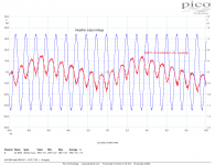
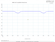
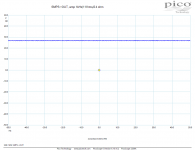
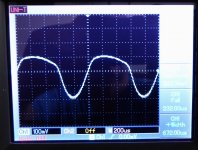
Basically it works as per attached image, but please note it is measured on another amplifier (class D) with another power (linear) supply. Rail voltage is measured AC coupled, so you can see the ripple voltage modulated by input frequency. The second and third plot show this amplifier (with SMPS) loaded with 2.4ohm with 20Hz and 1kHz signal, see the half-wave drops on the rail voltage (at 20Hz and 2.4ohm load the SMPS is close to current limit). The 1kHz plot should have been measured AC with higher sensitivity to see.
Attachments
PS rail modulation by load will end in the amplifier output attenuated by amplifier PSRR. Can it be major reason for odd harmonics domination? So far, I was able to find only claims/opinion that adequate PS will not determine amplifier’s distortion.
I have an A class amplifier with super regulators for PS. Measured distortion is slightly lower than declared by designer, but it can be attributed to other small differences in build.
This opens interesting question of what effect PS has on amplifier distortion.
I have an A class amplifier with super regulators for PS. Measured distortion is slightly lower than declared by designer, but it can be attributed to other small differences in build.
This opens interesting question of what effect PS has on amplifier distortion.
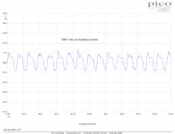
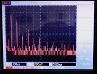
Just measured the SMPS rail modulation from 1kHz properly. Please see the time plot and spectrum attached. In the spectrum, one may see high H2 harmonic component which is supressed just by amplifier PSRR. Please note we are talking about -94dB to -100dB distortion components. Regardless this rail modulation effect on even harmonics, overall amplifier parameters are better with the SMPS than with the heavy linear power supply. It is time to leave prejudices formed by decades of audiophile discussions and popular magazine articles and reviews.
Attachments
I’m sold on idea that regulated PS is far better for an audio amplifier than unregulated CRC or CLC. Of course, transient response is very important.
SMPS is regulated PS, so no surprise that amplifier is better with it. Concerns about HF switching noise can be mitigated with inclusion of this excellent passive filter:
Murata filter
Filter is so small that it can be added directly on the amplifier PCBs and it’s all parameters are incredibly good (50V/20A, 0.5 mOhm, min. 45 dB attenuation. at 100 kHz).
There's no doubt that SMPS can be good for audio. Sony used them more than 30 years ago. Car amplifiers use them all the time, and some can achieve excellent performance (e.g. second generation Alpine PDX, but it is class D).
I notice that the local decoupling of the output stage is limited to 2x 100 µF which could probably be increased. Also, where does their ground go to?
Aside from that, I can imagine a cap across D6 will increase PSRR, and it will certainly decrease noise.
What is the imbalance of R6 and R7 at the operating point? Their supply is decoupled by C15, but is shared with the tail resistor R18 that might carry a substantial AC current. I wonder if replacing them with a current mirror and degenerating Q1 and Q2 to keep the open loop gain constant would improve PSRR.
That's great ! Please show some design of yours that illustrates this. Many thanks in advance... pursueing the best possible performance is what some of us strive for. ...
… and documented and provided with measurements. That’s what the projects and project threads are about.
- Home
- Amplifiers
- Solid State
- SAB - class AB 2x50W/4ohm amplifier with SMPS