Thanks for the clarification.
This is what Meanwell have to say about capacitive load :
https://meanwellpowersupplies.com/tag/capacitive-load/
https://meanwellpowersupplies.com/f...e-load-inductive-load-dynamic-load-peak-load/
"The principal issue that can appear on such type of load is at PSU start-up: a discharged capacitor basically acts like a short-circuit at start-up,
hence it may overload the output.
One solution is either to add current limiting resistors in series with the capacitive load to limit the output current,
or to select a power supply with “constant current limiting” overload protection type.
This way, the power supply will automatically limit the current to a certain level stated in the specifications."
So according to the above statement, one can add capacitance to the output when using e.g. the RSP series.
Patrick
Please forgive me for another silly question.
You mentioned using 2x Meanwell RS-100-24, wired in series, for +/-24V.
These two supply both channels, correct ?
The Meanwell output current is specified at 4.5A.
That means 2.25A per channel, if the above assumption is correct.
I guess 2x50W (rms?) 4ohm means +/-20V across 4R per channel.
That would mean 5A peak per channel, or 10A for stereo.
If we consider rms current only, I guess we still need 7A.
Where did I go wrong ?
Patrick
Per one supply and sine wave input the DC supply current is Idc = Imax(load)/pi, for 50W/4ohm Imax = 5A, Idc = 5/pi = 1.592A per 1 channel and one polarity (one supply). This makes 3.183A per 2 channels and one polarity. This is valid just for the push-pull class AB amplifier. One supply gives 4.5A so it can make it and it does. Remember that supply current per one rail looks like half wave rectifier plot.
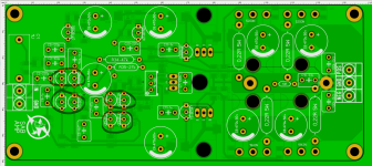
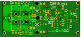
The thread has been covered in dust but I think it is an interesting topology that is worth mentioning. Here are some new measurements made with a common 2 x 25V power supply with bridge rectifier and capacitor filter.
THD 1kHz THD 10kHz
IMD 19+20kHz 10W
THD+N vs. power THD+N vs. frequency
All the plots are measured, NOT only simulated.
THD 1kHz
THD 10kHzIMD 19+20kHz 10W
THD+N vs. power
THD+N vs. frequency All the plots are measured, NOT only simulated.

You like to measure final designs and so do I.
Arguing with subjectivists, which prime “argument” is that measurements doesn’t tell “how it will sound”, I always say that it doesn’t take one measurement (they usually quote FFT) but as many as possible.
May I suggest that you add 31 or 32 tone measurement, like is standard for DACs. It is as close input signal to real music as it gets and it tells enough about IMD for complex signals and noise floor.
Interesting. At 20 W, 3rd and higher harmonics are really good but 2nd is not. Could this be an imbalance? The two diff pairs do not have current mirrors so their balance is at the mercy of part tolerances. Can you improve 2nd harmonic by making the Q11 current source adjustable?
What do the harmonics look like at 1 W or below? The THD vs. power plot imply an optimum at 0.1 W.
H2 level seems inherent to this kind of design, i ve played much with this topology and got about the same THD values whatever i did to improve the number, the values on the schematic are well thought overall.
A few things can be modded but they wont improve the final result, only thing i would point is that 65V BC546/556 should be used instead of 45V 547/557 for the pre drivers and everywhere else where there s a VCE that is close to the the supply voltage.
Now you understand which camp this amp falls into😉The thread has been covered in dust but I think it is an interesting topology that is worth mentioning. Here are some new measurements made with a common 2 x 25V power supply with bridge rectifier and capacitor filter.
THD 1kHzView attachment 1251774 THD 10kHzView attachment 1251775
IMD 19+20kHz 10W View attachment 1251776
THD+N vs. power View attachment 1251777 THD+N vs. frequency View attachment 1251778
All the plots are measured, NOT only simulated.
It should be OK with 2x35V, at least in simulation.how it will work with 35v?
However, regardless the PSU voltage 2x25V or 2x35V, I would strongly recommend to add output coil of 1uH in parallel with 6.8ohm resistor behind the output terminal.
- Home
- Amplifiers
- Solid State
- SAB - class AB 2x50W/4ohm amplifier with SMPS