Think it would be enough shielded if you could add vertical iron shields between amplifier modules and powersupply. Should be easy to get 2 iron plates at local suppliers...
Yes it is.Think it would be enough shielded if you could add vertical iron shields between amplifier modules and powersupply. Should be easy to get 2 iron plates at local suppliers...
BTW i have a question.
Is it safe the metal spacers usage(10mm long) mounting these 230vac boards ?
Like photo.
Attachments
Last edited:
Yes. Safety distances are checked....
Is it safe the metal spacers usage(10mm long) mounting these 230vac boards?...
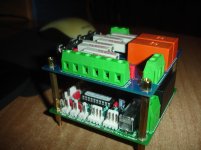

Perfect! Maybe it's better to mount the inrush current limit pcb at bottom. This reduces the risk of electric shock if case is open during maintenance. Also MCU boards 3rd NTC can be mounted directly at MCU board to check the inner case temperature near the top of the case.Control board(housekeeping) and inrush board.
BR, Toni
Ok Toni,i will mount this as your recommendations.
Given that the design is for a dual mono(separate transformers,rectifiers,caps bank), i wonder about the common usage of star ground and speaker returns on the housekeeping board.😕
Given that the design is for a dual mono(separate transformers,rectifiers,caps bank), i wonder about the common usage of star ground and speaker returns on the housekeeping board.😕
Last edited:
Now i have a dilemma, what is the preferable way for mosfets mounting?
As in picture 1 or in picture 2.
Can the first way,given more room to mosfets, ensures better cooling conditions?
Is it a danger for instability?
Mounting without some space can be dangerous....
Sajti
Attachments
For your version of mcu board just connect the mcu gnd via 2 pieces of 22 ohm resistor to each channels star ground. You need this only for dc detection.Ok Toni,i will mount this as your recommendations.
Given that the design is for a dual mono(separate transformers,rectifiers,caps bank), i wonder about the common usage of star ground and speaker returns on the housekeeping board.😕
Looks to be more the result of a bad design, bad or no mosfet matching, missing overcurrent protection or oscillation problems.😱Mounting without some space can be dangerous....
Sajti
Given that i haven't the output (speakers relays),what you think about using two general use speaker's protectors, keeping the mcu for all other function,on-off,inrush control,over temperature protection?For your version of mcu board just connect the mcu gnd via 2 pieces of 22 ohm resistor to each channels star ground. You need this only for dc detection.
Is this way more ground loop proof?
Something like this one.Omron relay / speaker protection board / support BTL amplifier | eBay
I seen the apdated index

Last edited:
It's better to use the MCU build in features because MUTE and SPKDC work together to keep the maximum safety for your speakers and your amplifier. All parameters can be configured in software. Temperature shutdown, mute delay, SpkDC sensitivity, auto shutdown with repowering avoidance, galvanic decoupled remote powering ...Given that i haven't the output (speakers relays),what you think about using two general use speaker's protectors, ...
BR, Toni
It's better to use the MCU build in features because MUTE and SPKDC work together to keep the maximum safety for your speakers and your amplifier. All parameters can be configured in software. Temperature shutdown, mute delay, SpkDC sensitivity, auto shutdown with repowering avoidance, galvanic decoupled remote powering ...
BR, Toni
Ok thanks,i will try finding the output relay pcb artwork,then i will come back with many questions about the mcu customisation.🙂
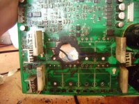
Looks to be more the result of a bad design, bad or no mosfet matching, missing overcurrent protection or oscillation problems.😱
Yes, it was a failure of the output device, but it kills the pcb too, if no distance..
Sajti
Are gerbers for the output relay published in the main thread?
Have a look at posts 1674 - 1689 before and after this post here:
housekeeping circuits - final hardware version 4.3
At post 1689 you can find gerbers.
BR, Toni
Last edited:
Yes, it was a failure of the output device, but it kills the pcb too, if no distance..
Looks like a design without any safety circuits - power supply delivered power and delivered power and delivered power ... 😱
MOSFETs tend to become a short circuit on failure. No fuse to stop those hazard?😎
Looks like a design without any safety circuits - power supply delivered power and delivered power and delivered power ... 😱
MOSFETs tend to become a short circuit on failure. No fuse to stop those hazard?😎
It was Crest Audio CC1800 amplifier, using BJT output, and quite sophisticated protection system. Maybe that BJT was weak...
Sajti
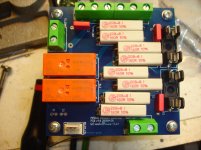
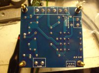
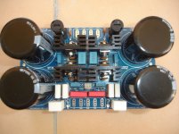
SA2015 Power Supply Boards.
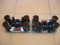
Two Power Supply modules ready for testing.
Top quality parts, easy mount, perfect footprint matching!
Congratulations Toni,very professional drawing😉 as usual🙂
Two Power Supply modules ready for testing.
Top quality parts, easy mount, perfect footprint matching!
Congratulations Toni,very professional drawing😉 as usual🙂
Attachments

Last edited:
- Status
- Not open for further replies.
- Home
- Amplifiers
- Solid State
- SA2015 V-MOSFET Builders