Peter Daniel said:Here how it's implemented in one of the very expensive product from a famous audio manufacturer. Somebody mentioned that: "Jocko will be amused about it.. "
Do NOT use this as an example of a good design. It is never good to drive a transmission-line with a Flip-flop. Even junior digital designers know this much....
Steve N.
Empirical Audio
Manufacturer
carlosfm said:
I'm installing clocks on cdps and transports since 1999.The Tent XO3 is a unique thing (as features go) and it has an amazing price/performance ratio.
It is better than any LC-Audio clock, and I tried' em all.
IMHO.
Have you tried Superclock2 or 3 from Audiocom international in the UK?
I have been modding for 3-4 years myself and I like these, although I further mod them.
Steve N.
audioengr said:
Do NOT use this as an example of a good design. It is never good to drive a transmission-line with a Flip-flop.
Steve N.
Empirical Audio
Manufacturer
why ?
Gee........sounds like he isn't buying any of yours any longer.................
I'm gonna stay outta this one........I've caused enough trouble to last me a few days.
Jocko
I'm gonna stay outta this one........I've caused enough trouble to last me a few days.
Jocko
"Am I looking at this the wrong way"
Yes.......the transformer is 100R on either end..........not 75R. At least not in the example you are looking at.
Jocko
Yes.......the transformer is 100R on either end..........not 75R. At least not in the example you are looking at.
Jocko
I was looking at just the Pi pad. Wich adapts the 100R to the 75R of the connector?
75R at the output // 137R +26,1R + 26,1R = 100,667R at the trafo, Seems right?
But seen from the other direction
100R at the trafo +26,1R + 26,1R // 137 = 72,1R at the output.
Wich seems a little low?
75R at the output // 137R +26,1R + 26,1R = 100,667R at the trafo, Seems right?
But seen from the other direction
100R at the trafo +26,1R + 26,1R // 137 = 72,1R at the output.
Wich seems a little low?
It might have something to do with the resistor values he had on hand. I don't remember.........senior citizen moment.
Jocko
Jocko
Guido Tent said:
why ?
1) because the internal feedback in a Flip-Flop is more sensitive to transmission-line reflections that can change it's state
2) because the drive strength of a Flip-flop is usually quite low.
3) It is not its intended use - use a driver to drive a transmission-line
Steve N.
Empirical Audio
audioengr said:
1) because the internal feedback in a Flip-Flop is more sensitive to transmission-line reflections that can change it's state
2) because the drive strength of a Flip-flop is usually quite low.
3) It is not its intended use - use a driver to drive a transmission-line
Steve N.
Empirical Audio
Hi Steve
1) Can be easlly solved by taking care of proper (series) matching. I've never seen that phenomena by the way.
2) Is not an issue when using it as a driver for SPDIF (transformer coupled)
3) The backend of a flipflop consists of a quasi PP output stage. At the risk of discussing definitions, I'd call that a driver.
best
Guido Tent said:
Hi Steve
1) Can be easlly solved by taking care of proper (series) matching. I've never seen that phenomena by the way.
2) Is not an issue when using it as a driver for SPDIF (transformer coupled)
3) The backend of a flipflop consists of a quasi PP output stage. At the risk of discussing definitions, I'd call that a driver.
best
Suit yourself. You can design it anyway that you like.
Steve N.
audioengr,
your statement:
sounds very convincing!!
Especially your respond in previous post sounds you are a more skilled debater than that your nickname suggests.
Ciao
your statement:
Do NOT use this as an example of a good design.
sounds very convincing!!
Especially your respond in previous post sounds you are a more skilled debater than that your nickname suggests.
Ciao
Calimero said:audioengr,
your statement:
sounds very convincing!!
Especially your respond in previous post sounds you are a more skilled debater than that your nickname suggests.
Ciao
The debating skills come in handy, but the 30 years of digital design experience is even more handy. Heard of the Pentium 2?
Steve N.
audioengr said:Have you tried Superclock2 or 3 from Audiocom international in the UK?
I have been modding for 3-4 years myself and I like these, although I further mod them.
Steve N.
When I bought my first clock back in 1999 the Audiocom (and also Trichord) was more expensive than the LC-Audio, and I opted for the later.
These were the days when you sent an e-mail and waited for a week (if you were lucky) for an answer, when somebody remembered to check the mailbox of the company.
No, I never tried the Audiocom clocks, I kept with LC-Audio until some years ago I tried the Tent clocks and never looked back.
LC-Audio is horribly expensive these days, and inferior to the Tent clocks IMO.
And it's a pleasure to buy from Guido, I can't say the same about LC-Audio.
audioengr said:Do the Tent clocks have 3.3V output? What about clock enable?
Hi
Yes, on request 3.3V is available
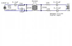
Katapum's RX input not right
I was just looking at Katapum's posting on the RX input and the impedance looking from the bnc connector is not 75 ohms. You will get better impedance match if you get rid of the 100ohm on the primary side, replace the 75ohm with 150ohm, and replace the 300ohm on the secondary with 150ohm. The zobel cap is around 22pf if the transformer leakage is ~0.5uH.
Experts, please comment if the calculations are right.
Thanks,
rlim
Attachments
Re: Katapum's RX input not right
this looks quite similar tom what we did a while ago
http://www.tentlabs.com/Products/DIYDAC/DIYDAC.html
I'd suggest a screen in the transformer to increase common mode rejection
best
rlim said:I was just looking at Katapum's posting on the RX input and the impedance looking from the bnc connector is not 75 ohms. You will get better impedance match if you get rid of the 100ohm on the primary side, replace the 75ohm with 150ohm, and replace the 300ohm on the secondary with 150ohm. The zobel cap is around 22pf if the transformer leakage is ~0.5uH.
Experts, please comment if the calculations are right.
Thanks,
rlim
this looks quite similar tom what we did a while ago
http://www.tentlabs.com/Products/DIYDAC/DIYDAC.html
I'd suggest a screen in the transformer to increase common mode rejection
best
1:4 transformer
Guido,
Looks like a 1:4 transformer is used. Jocko is gonna smackah your face.......
Guido,
Looks like a 1:4 transformer is used. Jocko is gonna smackah your face.......
Re: 1:4 transformer
🙂
actually it is 1:1+1, yes in terms of impedance that is 1:4
Yeah I know, but we learned in 10 yers. By then I liked the minicircuiits, now we have better ones like Scientificonversion and Schott.
best
rlim said:Guido,
Looks like a 1:4 transformer is used. Jocko is gonna smackah your face.......
🙂
actually it is 1:1+1, yes in terms of impedance that is 1:4
Yeah I know, but we learned in 10 yers. By then I liked the minicircuiits, now we have better ones like Scientificonversion and Schott.
best
Not only don't 4:1 transformers work, but screens don't either.
Unless you don't care about reflections. I know you do.................
There is a reason that the secondary is loaded to 300R...................so there.
Jocko
Unless you don't care about reflections. I know you do.................
There is a reason that the secondary is loaded to 300R...................so there.
Jocko
- Status
- Not open for further replies.
- Home
- Source & Line
- Digital Source
- S/PDIF Digital output