OK....now let's think about how you are actually going to construct it.
Let's assume that you have an honest to goodness BNC connector. A 75 ohm one at that!
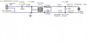
I would solder a 137R SMD right at the pins of the connector. Take a 26R1 SMD from each pin back to the trafo. Use 158R and 221R SMD types on the other end, although you can have some stray inductance there without as much degradation.
I did not calculate the pad values, but it can be a little bit high without having to worry about blowing the protecton diodes in the RX front end, or worse, creating tons of EMI.
If you do have EMI issues, you can place a 0.1 uF or so cap from the cold (shield) end of the connector to earth. I advise using an insulated BNC, to make sure that you do not have a ground loop. (That is part of the reason for using a trafo.)
Class is about over.........you did well.
Jocko
Let's assume that you have an honest to goodness BNC connector. A 75 ohm one at that!
I would solder a 137R SMD right at the pins of the connector. Take a 26R1 SMD from each pin back to the trafo. Use 158R and 221R SMD types on the other end, although you can have some stray inductance there without as much degradation.
I did not calculate the pad values, but it can be a little bit high without having to worry about blowing the protecton diodes in the RX front end, or worse, creating tons of EMI.
If you do have EMI issues, you can place a 0.1 uF or so cap from the cold (shield) end of the connector to earth. I advise using an insulated BNC, to make sure that you do not have a ground loop. (That is part of the reason for using a trafo.)
Class is about over.........you did well.
Jocko
And now what is the best way to implement the design
Jocko and other clock experts,
Can you shine you ligh on the following:
what is the way to implement a SPDIF-design, based on a trafo (and of course a 75ohm BNC connector) given the distance between chasis and the SPDIF-source (is i.e in case of the design in this thread SA7720 pin 14) is say 20cm.
I see 3 schemes:
1) the distance between BNC connector and trafo is kept as short as possible or
2) the distance between SA7720 pin 14 and trafo is kept as short as possible or
3) the distance is both kept 10cm.
what is the impedance of the trafo seen by the SA7720 or the logic driving the trafo? (is it 75ohm??).
I ask because to determine what wire can best be used to connect the driver to trafo in case 1 and 3.
What are the aspects tht play a role to decide between one of the referred schemes?
--
I lack the theoretical backgroundand to make a carefully thought-out decision.
However if I had to proceed with trial and error I would start by implementing scheme 1 and use normal wire (twisted) to connect the SPDIF-source to the trafo.
My explanation would be that the SPDIF-source is TTL-logic, which is not that critical to connect over longer distances. 🙄
Is this correct???
Calimero,
I am not an expert, and I did not pass the class exam yet like katapum did 🙂
But, the main thing is to avoid signal reflections in the data channel.
Reflections can "smear" the changing edges between logical levels, and make the timing less defined at the receiver side, the place where one would like to reconstruct the data stream with precise timing [so as to be able to extract a low jitter clock].
You can do it by using a controlled impedance transmission line, because in such a line [if it's terminated properly] there are no reflections generated. The twisted pair connection between the ttl output and the transformer is not such an environment, so you can not guarantee the signal integrity. The solution is to keep the "undefined" path length as short as possible, and resolve everything in a controlled impedance way. So, the driver & trafo described above should be very close to the driver IC, and you should travel the 20 cm-s with a 75ohm cable. The problem is that also the pigtails on the cable are a threat, at both ends. In professional ambient they use an "I" pass-through connector [75ohm] on the back panel of the instrument, and a short cable [20cm] with a crimped on bnc connector at the "I" end, and a very tigthly executed panel connection at the transformer & driver end.
From outside one would only see the usual bnc output connector..
It sounds complicated, but in the reality it's not so much so..
This is the best way, all the others are some kind of a tradeoff.
For example, instead of the "I" one can use standard isolated panel bnc connector, but trim the pins very short, and use the smallest pigtail possible.
Though I would like to add: If you use a direct SPDIF output from the SA chip, and do not re-clock it, then You can use any of the setups, will not see the difference.. The inherent jitter of the SA will be in any case much worse than the deterioration caused by the cable.
Now I hope the real experts will correct me..
Ciao, George
You have a straight answer with a ...
sound (and understandable) explanation, and that is what counts for me. Thanks
I will definetly not output the SA7720 SPDIf signal without reclocking. I ask because I have a Proceed CDP with a Tent-clock X02, where I haven't yet optimise the SPDIF-connection. The output is wired (using twisted pair) to a standard isolated panel bnc connector. I can't hear the different between the SPDIF-output of the Proceed and the SPDIF-output of the tent-clock, but it is clear why that isn't heard. I'll try your scheme this weekend and report back on the results.
Thanks Henk
Uhm, now I'm a bit confused - I've always thought the XO3 is the one with a re-clocked SPDIF output. But, if you use that, then the most ideal solution would be to put [build out..] the XO2 - XO3 directly on the backpanel BNC pins, or very close to it, and travel with the twisted pair from the SA chip to it.. So the "smear" caused by the mixed connections and wires will be "cleaned up" at the reclocker and sent out to the SPDIF.
Oh, I see, with the XO You want to stay close to the Dac..
Well, life is difficoult..
Ciao, George
Oh, I see, with the XO You want to stay close to the Dac..
Well, life is difficoult..
Ciao, George
Joseph K said:I've always thought the XO3 is the one with a re-clocked SPDIF output.
Yes it is, and it's a fantastic clock.
Joseph K said:But, if you use that, then the most ideal solution would be to put [build out..] the XO2 - XO3 directly on the backpanel BNC pins, or very close to it, and travel with the twisted pair from the SA chip to it..
When I can't position the clock very near the chip and/or the SPDIF plug, I use 75ohm mini-coax cable, instead of the twisted pair.
George,
I have a Tent X0-3, which has the reclocker and pulse trafo add-on. It is build in my Proceed CDD (instead of CDP), which is a transport.
In this case the scheme is to place the X0-3 as near as possible to the Chassis and that way keep the connection to the BNC-connector as short as possible. The longer wires for the clock in the transport are less critical as I understand.
Carlos, I agree it is quality product, have not copared to any other clocks (but my friend audiofanatic has and reported ......).
Thx Henk
Calimero said:Carlos, I agree it is quality product, have not copared to any other clocks (but my friend audiofanatic has and reported ......).
Thx Henk
I'm installing clocks on cdps and transports since 1999.The Tent XO3 is a unique thing (as features go) and it has an amazing price/performance ratio.
It is better than any LC-Audio clock, and I tried' em all.
IMHO.
Originally posted by Jocko Homo
THANKS Jocko Homo.
Katapum
Class is about over.........you did well.
THANKS Jocko Homo.
Katapum

You are not using that HUGE audiophile grade film cap in the circuit, are you?? Too much inductance, I'm sure.
As for the RX side..........you eventully are going to hit some active stage, right? What is your goal/aim/purpose?
Jocko
As for the RX side..........you eventully are going to hit some active stage, right? What is your goal/aim/purpose?
Jocko
Hi,
HUGE? Should I build it with a ceramic or a MKT cap?
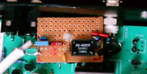
I have all parts to build your input S/PDIF schematic but …one more PSU in my DAC (my dac has “only” 9)…so I´d like to build a better and all-passive S/PDIF dac input. Is it possible? (Att. picture is my dac input.)
Katapum
HUGE? Should I build it with a ceramic or a MKT cap?
I have all parts to build your input S/PDIF schematic but …one more PSU in my DAC (my dac has “only” 9)…so I´d like to build a better and all-passive S/PDIF dac input. Is it possible? (Att. picture is my dac input.)
Katapum
Attachments
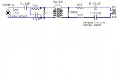
I would rather use a small stacked foil type (0,1 uF), and bypass it with a 1 nF C0G/NPO type.
You do not need the coupling cap on the input side if you have a trafo on the TX side.
Yes, it work without a buffer, but it will work better with one. See my (many) previous rantings about that.
Jocko
You do not need the coupling cap on the input side if you have a trafo on the TX side.
Yes, it work without a buffer, but it will work better with one. See my (many) previous rantings about that.
Jocko
Hi,
First I will try without a buffer. Should I remove all the parts between C1/2 and Crystal chip?
Katapum
First I will try without a buffer. Should I remove all the parts between C1/2 and Crystal chip?
Katapum
Hi,
Originally posted by Jocko Homo
Yes, it work without a buffer, but it will work better with one. See my (many) previous rantings about that.
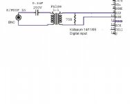
I not found much about a passive spdif input so I made a mix between yours and NP (D1 dac) spdif input.
Katapum
Originally posted by Jocko Homo
Yes, it work without a buffer, but it will work better with one. See my (many) previous rantings about that.
I not found much about a passive spdif input so I made a mix between yours and NP (D1 dac) spdif input.
Katapum
Attachments
Hi all,
I finished all spdif mods.
I built:
A new digital output (my schematic);
A new all 75 Ohm long long interconnector;
A new active digital input (JH schematic).
It’s one of the best modifications I ever made. I never expected these results. Seems I have a new CD collection. Detail/precision level is impressive. Thanks to all and in particularly thanks to Jocko Homo.
Katapum
I would solder a 137R SMD right at the pins of the connector. Take a 26R1 SMD from each pin back to the trafo.
75//137 +26,1 +26,1 = 100,667R
But
(100+26,1+26,1)//137 = 72,1R
Am I looking at this the wrong way or is there more optimal values availble?
- Status
- Not open for further replies.
- Home
- Source & Line
- Digital Source
- S/PDIF Digital output