They also assume a 0ohm output impedance from the flipflops. And the Q´ is used to get a balanced signal.
Jocko Homo said:Hifi gets another gold star.
After examples of internal S/PDIF, and taking a digital output directly out of a 2-pin plug of a Samsung CDROM, that's high-end.

hifi said:I dont recall ever owning a Samsung cdrom
Huh? 😕
I was talking about the Audio Analogue Primo CDP, discussed on a recent thread.
Aha, nevermind I thought
Was referred to me
After examples of internal S/PDIF, and taking a digital output directly out of a 2-pin plug of a Samsung CDROM, that's high-end.
Was referred to me
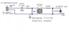
4R7+25R // 4R7 will not give you 75R
326R+25R // 95R3 would give you 75R and roughly the same attenuation as the original circuit.
163R+25R // 125R will still give you around 75R but only about half the attenuation of the first circuit.
Then after the transformer you attenuate with say a H-pad.
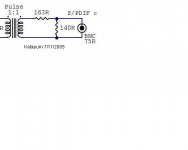
326R+25R // 95R3 would give you 75R and roughly the same attenuation as the original circuit.
163R+25R // 125R will still give you around 75R but only about half the attenuation of the first circuit.
Then after the transformer you attenuate with say a H-pad.
hifi said:Was referred to me
😕
http://www.diyaudio.com/forums/showthread.php?postid=754852#post754852

How?? I have a TDR. Philips would be the last guys that I would expect to know. Even if they did, look at the horrible circuits they have. The worst trafo known to man, and who knows how much mystery wire between the actual circuit and the RCA jack.
Speaking of which............no RCA jacks!
H-pad looks like an "H". You have an "L- pad".
H-pad, or pi-pad would be best.
BUT.............
I would not run the trafo directly from the chip. Insert some R to limit current. And a C to keep DC form the trafo (very important!)
So....you have to add the 25R or so with the series R before you can design the H-pad.
If you go pi-pad, you can either put the shunt leg at the secondary, or at the output side. You have lots of options. A lot will depend on what nice resistor values work out. Yes, it is not as easy as it seems. We could be at this for a while, but you should learn a lot.
Maybe hifi wants to design the pad(s). He seems capable.
Jocko
HI,
Originally posted by Jocko Homo

Katapum
Originally posted by Jocko Homo
So....you have to add the 25R or so with the series R before you can design the H-pad.
Maybe hifi wants to design the pad(s). He seems capable.
Katapum
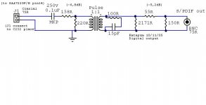
Attachments
Everything is at your hands ...
you only need some initiative at your side and creative googling.
You should by now know the guys here aren't willing to tell you the whole story, although they provide you with enough hints to put you on the right track.
Therefor try googling with terms as:
- "H-pad"electronics
- "H attenuator" design
It is a pitty the search engine of this site is useless (you would wonder why that is the case).
However I know a usefull link that shows an example of what you are looking for.
It is: http://www.diyhifi.org/forums/viewtopic.php?t=284&start=120
Let us know your results after you have implemented it and heard the results.
Henk
Hi Katapum,
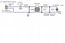
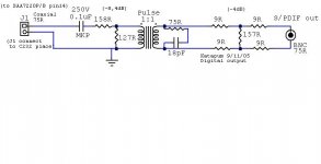
although I haven't calculated the output impedance your 75ohms attenuator is faulty, as the output impedance is always less than 62 ohms.
although I haven't calculated the output impedance your 75ohms attenuator is faulty, as the output impedance is always less than 62 ohms.
Jocko Homo said:Hifi moves to the front of the class for paying attention.
😀
bocka said:Hi Katapum,
although I haven't calculated the output impedance your 75ohms attenuator is faulty, as the output impedance is always less than 62 ohms.
🙄

Not bad.............
You may want to try a different version. It does not have to be 75 ohms on either side of the transformer.
You could make it...........say...........100 (just for conversation sake) on either side. The zobel would have to be for 100 ohms. The pad would then have to look like 100 ohms back to the chip, and 75 ohms out to the line.
Making the Z on the drive side makes a nicer looking trace on the TDR. (Don't ask me to explain, just trust me for now.) Also allows you to make the pad a higher value. Which is a good thing.
Jocko
Should be......but I did not check all the impedances.
Try rotating the pi-filter 90 degrees clockwise.............!
Jocko
Try rotating the pi-filter 90 degrees clockwise.............!
Jocko
- Status
- Not open for further replies.
- Home
- Source & Line
- Digital Source
- S/PDIF Digital output