Jocko Homo said:Comment: I don't like it.
Jocko
would be nice to hear why and what you suggest ?
regards
doede
A good starting point is:
http://www.diyhifi.org/forums/viewtopic.php?t=284&postdays=0&postorder=asc&start=90
Henk
http://www.diyhifi.org/forums/viewtopic.php?t=284&postdays=0&postorder=asc&start=90
Henk
Jocko Homo said:I have already done that, many times, but let's start here:
What is the ouptput impedance?
Jocko
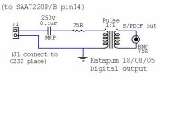
Ops... that signal is not attenuated to SPDIF (0.5V p-p) level...

Impedance? Not 75R for sure.
At least 2 of you guys have been paying attention.............
OK, assuming that he fixes those problems, what transformer is it?? All pulse transformers are not created equally. Most are useless for SPDIF.
If you don't believe me, try the one that comes stock in Philips CPDs. Designed to minimise EMI, not performance.
Jocko
OK, assuming that he fixes those problems, what transformer is it?? All pulse transformers are not created equally. Most are useless for SPDIF.
If you don't believe me, try the one that comes stock in Philips CPDs. Designed to minimise EMI, not performance.
Jocko
Many 100 Mbit/s ethernet pc cards have a pulse transformers at their input. Are they useful for SP/DIF?
Paul
Paul
The Pulse is not a bad choice.
You need to figure out the Z of the chip, take that into account, and pad down the ouptut. That is one way, probably the easiest.
Never looked at any of the trafos you ention. Would not be surprised if they aren't that good. I know, you would think so.............
If someone has some pull-outs, send them to me, and I can measure them.
Edit:
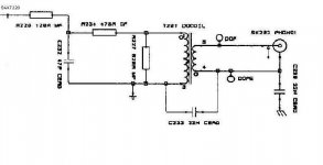
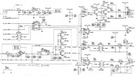
I see where you posted a schematic. A bit hard to read..........looks like something Philips would do. Nope, I like it even less.
Jocko
You need to figure out the Z of the chip, take that into account, and pad down the ouptut. That is one way, probably the easiest.
Never looked at any of the trafos you ention. Would not be surprised if they aren't that good. I know, you would think so.............
If someone has some pull-outs, send them to me, and I can measure them.
Edit:
I see where you posted a schematic. A bit hard to read..........looks like something Philips would do. Nope, I like it even less.
Jocko
Well, you didn't tell me that you are a "noob".
OK, figure it is around 25 ohms. Close enough for this circuit. A few ohms either way is closer than 0, which is what you.....and some famous audio designers........planned on.
At least you are not a professional, and have nothing to feel ashamed about. They are, and should be.
(Now you know more than they do! Don't tell them: their egos won't allow it.)
Jocko
Katapum said:Last try:
I don't think so. 😀
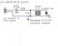
You didn't understand... count with around 25 ohm output impedance for the 7220.
Adjust the resistors accordingly.
Btw remember to take rounding to nearest obtainable resistor values into account.
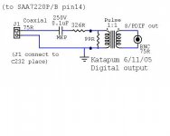
Maybe you could also try padding down the signal after the transformer (after getting it terminated to 75R first) to get the added benefit of also reducing reflections.
Maybe you could also try padding down the signal after the transformer (after getting it terminated to 75R first) to get the added benefit of also reducing reflections.
Alternatively you could build it and then shock horror ....listen to the results.
I've had some good results using pulse trans. in the digital line, and fitted a few to cdp's and dac's I've played with.
I've had some good results using pulse trans. in the digital line, and fitted a few to cdp's and dac's I've played with.
- Status
- Not open for further replies.
- Home
- Source & Line
- Digital Source
- S/PDIF Digital output